John Jay based in Georgia, USA is a retired engineer who’s “gotten the PI bug” and designed some new IO boards for the Raspberry Pi. He’s currently selling them via eBay and I have some here to play with!
(I love new toys!)
So-far he’s designed a simple buttons and LED board, a stepper motor driver (although it’s really a versatile 8-bit output port with a ULN2803 darlington driver) and the third is a 32-bit GPIO extender board
The one I’m looking at today is the the buttons and LEDs board – very similar to my Ladder board, but in some ways much simpler and more down-to earth.
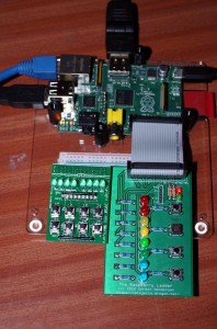
His boards are very small and designed to sit on-top of the Raspberry Pi. Here is the button/LED board next to my Raspberry Ladder board and on top of a Raspberry Pi:
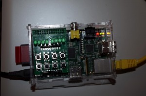
The board plugs into the Pi (please do it while your Pi is turned off!) and there is a rubber bumper underneath to stop it wobbling and potentially shorting anything out underneath (a problem I noticed in some other boards – thankfully most people have seen the light now and are supplying these little bumpers on their boards)
The board itself presents no issues when using. John has used the switches with the long buttons which make them easier to use than the low-profiles ones. The board has the standard BCM_GPIO numbers on it – so you need to do some conversions if you are using a Rev. 2 Pi as numbers 0,1 are now 2 & 3, and 21 is now 27.
The (very bright!) LEDs have 330Ω limiting resistors and the switches connect to ground via a 1K resistor, so like my ladder board, it’s important to set the internal pull-up resistors on the Pi to read them reliably. (and the 1K resistors will prevent any damage should the pins be accidentally configured as output)
I wrote this little test program to quickly check the boards functions:
/*
 * jjLed.c:
 *      Test program for John Jays LED and Button board
 *      Gordon Henderson
 *
 * The board is laid out as follows:
 *
 * LEDs:      ( 8) ( 9) ( 7) (11)  (10) (13) (12) (14)
 *
 * Switches:     [16]      [ 0]       [ 1]      [ 2]
 *               [ 3]      [ 4]       [ 5]      [ 6]
 *
 * Numbers here are wiringPi pin numbers and will work on either
 * a Rev1 or Rev2 Raspberry Pi
 *
 ***********************************************************************
 */

#include <stdio.h>
#include <wiringPi.h>

static int leds [8]    = {  8,  9,  7, 11, 10, 13, 12, 14 } ;
static int buttons [8] = { 16,  0,  1,  2,  3,  4,  5,  6 } ;

int main ()
{
  int i ;

  if (wiringPiSetup () < 0)
  {
    fprintf (stderr, "Unable to initialise wiringPi\n") ;
    return 1 ;
  }

  for (i = 0 ; i < 8 ; ++i)
  {
    pinMode (leds    [i], OUTPUT) ;
    pinMode (buttons [i], INPUT) ;
    digitalWrite    (leds    [i], LOW) ;
    pullUpDnControl (buttons [i], PUD_UP) ;
  }

  for (;;)
    for (i = 0 ; i < 8 ; ++i)
      digitalWrite (leds [i], !digitalRead (buttons [i])) ;
}
I saved this into jjLed.c and compiled with:
gcc -Wall -ojjLed jjLed.c -lwiringPi
and run with:
sudo ./jjLed
and it worked a treat – pushing the buttons resulted in the corresponding LED being lit up while it was pushed – the top 4 buttons control the left-most 4 LEDs and the bottom 4 buttons control the right-most 4 LEDs.
John has a website which is in the process of being put together right now, (see mypishop.com) and is selling these on eBay and for $9.99 it’s not a bad deal at all and a good introduction to the Pi’s GPIO.


