The Gertboard has an on-board Digital to Analog (DAC) converter and an Analog to Digital (ADC) converters. These are connected via the SPI bus back to the Raspberry Pi host.
Each of the DAC and ADC chips has 2 channels.
The DAC has a resolution of 8 bits and produces an output voltage between 0 and 2.047 volts, the ADC has a resolution of 10 bits and can take an input voltage between 0 and 3.3 volts.
Part of the wiringPi library includes code to setup and drive these chips in an easy to use manner. Get wiringPi here.
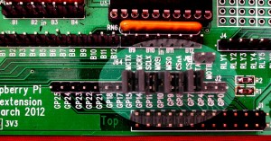
To use in a C/C++ program, first you need to make sure that the 5 SPI jumpers are present on the Gertboard (there are 7 in total, 5 for the SPI, 2 to connect the serial to the ATmega) – the photo below shows all 7 jumpers in-place.
In your C/C++ program you also need to:
#include <gertboard.h>
and compile with
cc -o myProg myprog.c -lwiringPi
The following functions are available:
- int gertboardSPISetup (void)
This must be called to initialise the SPI bus to communicate with the Gertboards ADC and DAC chips. If the return value is < 0 then an error occurred and errno will be set appropriately.
- int gertboardAnalogRead (int channel)
This returns a value from 0 to 1023 representing the value on the supplied channel (0 or 1). To convert this to a voltage, use the following formula:
vIn = value * 3.3 / 1023
- int gertboardAnalogWrite (int channel, int value)
This outputs the supplied value (0-255) to the given channel (0 or 1). The output voltage is:
vOut = value / 255 * 2.047
or to find the value for a given voltage:
value = vOut / 2.047 * 255
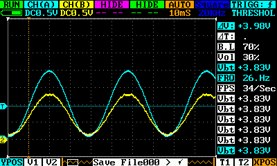
The sample program in the wiringPi examples directory; gertboard.c is designed to output a sine wave on DAC channel 0, then reflect whatever comes into ADC channel 0 to DAC channel 1. So if you loop DAC output 0 to ADC input 1 while running this program and connect an oscilloscope to the DAC outputs, then you should get this:
The cyan trace is the output from DAC 0 (0 to 2.047 volts), and the yellow trace is the output from DAC 1 – which is smaller as the 2 volt, 8 bit output is scaled.


