Before we can start to program the ATmega, we need to initialise the chip. The chip itself needs to be told about various parameters such as it’s clock speed, how much flash to reserve for the bootloader (none in our case) and so on.
This is known as “programming the fuses”.
The first thing to do is to connect the Gertboard to your Raspberry Pi and install 4 jumper wires from the Pi’s GPIO to the ATmegas ISP port. The manual has a much better picture than my photos show below, however:
The wires to connect up are as follows:
- GPIO pin 8 -> ISP pin 5 (RESET)
- GPIO pin 9 -> ISP pin 1 (MISO)
- GPIO pin 10 -> ISP pin 4 (MOSI)
- GPIO pin 11 -> ISP pin 3 (SCLK)
The obvious down-side of doing it this way is that you can’t use the Raspberry Pi’s SPI interface when developing code for the ATmega. Hopefully this will not be an issue.
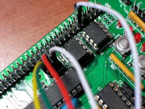
Some photos to help visualise the connections:
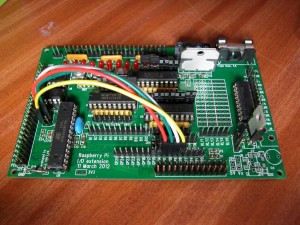
This is an overall picture of the Gertboard with the GPIO ribbon cable removed so you can see what’s happening.
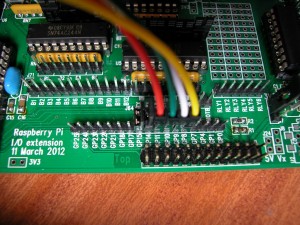
This is a close-up of the Raspberry Pi’s GPIO side. The 4 wires are Red (GPIO 11; SCLK), Green (10; MOSI), White (9; MISO) and Yellow (8; RESET) The two photos are taken from each side of the board. You may have to remove the 2-pin jumpers from the Gertboard to make the connections.
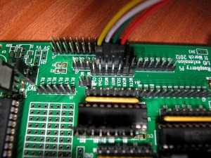
This is the other end of the wires – White is pin 1 (MISO), Red is pin 3 (SCLK), Yellow is pin 5 (RESET) and Green is on pin 4 (MOSI) Note that there are 2 unused pins on this connector, the top and bottom pins on the right-hand side. Please do not connect to these pins – they are connected to +3.3v and 0v respectively.
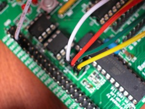
Another view of the above. Ignore the additional white wire on the right-hand side…
Once that’s done, connect the Gertboard to the Pi and power up. Once Linux has booted on the Pi, then run the avrsetup command.
avrsetup
You will be propmpted for the type of ATmega microcontroller; 1 for an ATmega 328p or 2 for the ATmega168.
If this command works OK, you should see the following:
Initialising a new ATmega microcontroller for use with the Gertboard.

Make sure there is a new ATmega chip plugged in, and press
.. 1 for an ATmega328p or 2 for an ATmega168: 1
Initialising an ATmega328p ...
Looks all OK - Happy ATmega programming!
And that’s it. You can now run-up the ardunio IDE and start to use it to send code into the ATmega microcontroller.

