
Blink is a very simple introduction to hardware interfacing. The task is simple: Make a light blink on and off…
This page will take you through the steps required to achieve a blinking light connected to your Raspberry Pi. We will take a bottom-up design approach to the problem. ie. we will start with a very simple system and build and test the eventual solution on-top of this, as we go.
A few assumptions to start with though: You will need a functioning Raspberry Pi running the Raspbian operating system. You’ll need in physically close to you and either have it connected directly to a screen and keyboard, or be using another PC to access it via either SSH or VNC.
The Raspberry Pi will need the wiringPi software package installed. It should be already installed, but if not then the command:
sudo apt-get install wiringpi
should install it. (You will need an Internet connection to do this)
What we also need:
- A solderless breadboard – this is an electronics prototyping device that lets you connect components to each other without soldering.
- Some jumper wires – wires that will connect the Raspberry Pi to the breadboard.
- An LED. This can be a simple 3 or 5mm LED.
- A resistor. More on this later.
The LED
LED: Light Emitting Diode. This is a semiconductor device that gives off light when a current is passed through it. Give it too much current and it will be very bright – for a very short period of time. This is where the resistor comes in. It throttles the current. The value of the resistor needs to be calculated to work with the LED and the Raspberry Pi’s 3.3v output signals. Fortunately for most common red/green/yellow LEDs you can simply multiply the voltage by 100 to get the resistor value in ohms. So we need a 330 ohm resistor.
One important thing to note with LEDs is that the only work one way round (that’s the diode part). Fortunately they usually come with 2 ways to work out which way round the go. The first and easiest way is to look at the length of the wires – one will be longer and this is the one to be connected to the positive side of the circuit. The other way is to look at the actual LED itself – and you’ll see its not perfectly circular, but has a flat edge. This is next to the wire that you connect to the negative side (or 0v or Ground/Gnd).
The resistor can be before or after the LED – it doesn’t matter, and it can be positioned either way round. That doesn’t matter either.
Light the light
Starting at the very bottom, before we write any programs or do anything else to try to make the LED blink, we need to make sure the LED works and that its connected the right way round. Fortunately the Raspberry Pi provides a constant 3.3v supply that will let us do this without needing to do anything on the Pi other than turn it on.
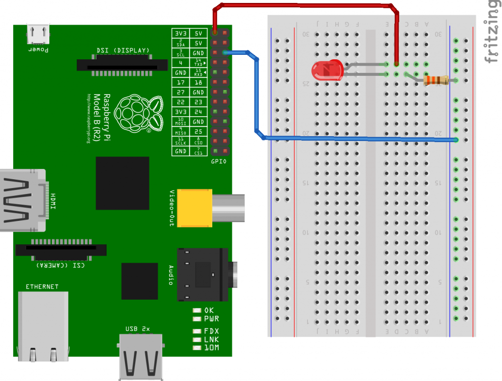 Blink diagram – LED testing
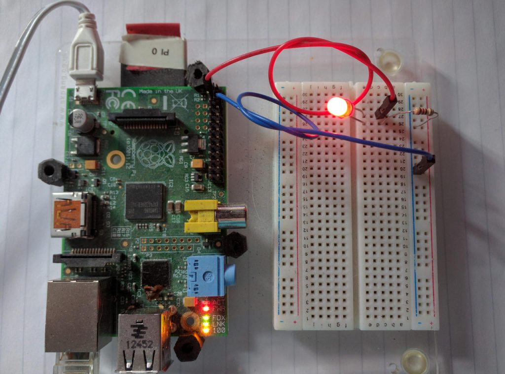 Blink photo – LED testing
This diagram and photo shows how to wire up the LED and resistor to the Pi. The Pi shown is an older model with a 26-pin GPIO connector – this still works if you have a newer one with a 40-pin connector as the pins are extended without affecting the first 26 pins.
Once you get the LED to light, then we can move on to get the Pi to control the LED by moving the Red wire to one of the controllable pins on the GPIO connector. This is part of the bottom-up philosophy – start at the bottom with something simple, make it work, then build on-top of it. A bit like building the foundations of a house… No point designing the penthouse without something to put it on!
Control the light
Now that we have the LED lit up using the Pi’s 3.3v supply, we need to move the wire from the power supply to one of the GPIO pins. We’ll use what’s generally know as the first usable pin, however it’s no-where near the first pin on the connector.
In a terminal, run the command:
gpio readall
To get a printout of the GPIO connector for your Pi. You are looking for a pin labelled GPIO.0.
Note: The gpio command is part of the wiringPi package and is a useful tool that lets you do ltos of things with the GPIO pins on the Raspberry Pi. You can use it from the command-line or inside simple shell scripts and programs.
Now we have a choice of how we refer to that pin in our programs. There are three different ways to number these pins. The easy way is to use the pin number on the connector, but to do this, you need to know how the connector is numbered. Look at the central 2 columns in the output of the gpio readall command to see these numbers. Our GPIO.0 pin is pin number 11. Sometimes called physical pin 11. Other ways to refer to this pin is by the pin number that’s used in the internal GPIO controller and in this mode, it’s pin 17. The final way is the native wiringPi method and this is pin number 0 in wiringPi mode. wiringPi pin mode is easy to use, but not very popular.
Move the red wire to this pin. The LED should be off at this point. To turn the LED on, we need to do 2 things. The first is to tell the hardware to make the pin an output pin (they are input by default) and the second is to tell the hardware put put 3.3v on the pin while its in output mode.
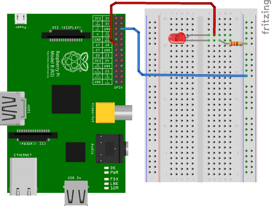 Blink diagram – Pi control
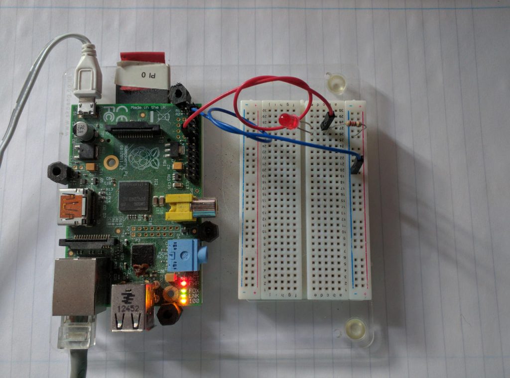 Blink Photo – Pi Control
The first command:
gpio -1 mode 11 output
this will make sure the pin is in output mode, then:
gpio -1 write 11 1
This will set pin 11 to logic 1 – which is 3.3v.
We’re adding -1 to the command. This tells the gpio command to use physical board numbers. (The ‘1’ comes from the original Pi when the GPIO connector had the label “P1”)
To turn the LED off:
gpio -1 write 11 0
This will set the output to logic 0, or 0v.
If you get this far and the above works, then we need to write a program to make the LED blink. There are 1000’s of programming languages you can use, but we’ll do it simply by writing a shell script (also called a bat or batch file in other systems) that will use the gpio command.
Use the nano command to create a new file:
nano blink.sh
nano is a simple text editor – like notepad in Windows. Enter the following lines of text:
echo Blink

gpio -1 mode 11 output
while true; do
  gpio -1 write 11 1
  sleep 0.5
  gpio -1 write 11 0
  sleep 0.5
done
Once you have done this, press Ctrl-X to write the file and exit. Just follow the prompts.
Blink!
To run this script type:
sh blink.sh
and there you have it. Press Ctrl-C to stop the script running.