At the heart of the hardware version of the ladder game is a 555 timer to generate a square wave, a single capacitor, some resistors and a switch. Our task is to emulate this in software – Allow it to charge when the button is pushed (but only if the LED is lit!) and to discharge it immediately if the button is still pushed when the LED goes off.
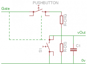
The simulated circuit looks something like this:
The idea is that the capacitor is continually discharged (slowly) by R-DIS, but when you push the PUSHBUTTON it’s charged – but only while the Gate signal is high. When the Gate signal goes low the charge stops – however the added twist is that if you are still pushing the button when the Gate is low, then the switch S1 is activated, completely discharging the capacitor immediately. R-CHG is an order of magnitude lower than R-DIS, so we can achieve quite a high charge on C1. Gate is initially going to be at about 2Hz, but it will get faster and faster in proportion to the charge on C1… vOut is connected to a (simulated) analog to digital converter and to the bank of LEDs to represent the voltage on the capacitor. (with a bit of extra logic to make the top one flash!)
The charging voltage is given by the standard potential divider calculation:
vCharge = r2 / (r1 + r2) * vBatt
Standard capacitor charge formulae:
vCap = (vCapLast - vCharge) * exp (-T / R*C)) + vCharge
and discharge:
vCap = vCapLast * exp (-T / (R*C))
vCap is the voltage over the simulated capacitor, vBatt is the “battery” voltage (volts), vCharge is the (maximum) available voltage at the capacitor, T is the time period (seconds), R is the resistance (ohms) and C is the capacitance (Farads)
Using these, we can start to build our simulator, but we’ll make a few assumptions first. vBatt will be 9 volts because the original was powered by a PP3… The simulated capacitor will be 1000μF and the charge resistor will be 2200Ω with the discharge one being 68KΩ
These can be adjusted if desired but in the interests of authenticity, I decided to stick to standard E12 “preferred” resistor values.

