Part of wiringPi is a library to allow access to parallel interface LCD displays (Those that use the popular Hitachi HD44780U or compatible controllers)
The library is simple to use in your own programs, however wiring the displays up may be challenging, so do take care. It is possible to wire up more than one display! In 8-bit mode, the first display needs 10 GPIO pins and each additional display needs just one more pin, so with a maximum of 17 GPIO pins, that’s 8 displays. If you move to using a 4-bit interface (trivial in the code), then it’s 4 more displays – 12 LCDs! However I suspect the rest of the wiring might be somewhat challenging… Wiring is described at the end of the this page.
The LCD display can be either a 5V display or a 3,3v display, however if we are using a 5V display then we must make absolutely sure the display can never write data back to the Raspberry Pi, otherwise it will present 5V on the Pi’s GPIO pins which will not be good. At best you’ll destroy the pin drivers, at worst you’ll destroy your Pi.
So make sure you always connect the R/W pin on the display to ground to force the display to be read-only to the host.
To use the LCD library, you’ll need this at the start of your program:
#include <wiringPi.h>
#include <lcd.h>
First, you need to initialise wiringPi in the way you want to. The LCD library will call pinMode functions, but these are ignored if you have already set the modes using the gpio program and want to use the wiringPiSetupSys() mechanism.
- int lcdInit (int rows, int cols, int bits, int rs, int strb,
int d0, int d1, int d2, int d3, int d4, int d5, int d6, int d7) ;
This is the main initialisation function and must be called before you use any other LCD functions.
Rows and cols are the rows and columns on the display (e.g. 2, 16 or 4,20). Bits is the number of bits wide on the interface (4 or 8). The rs and strb represent the pin numbers of the displays RS pin and Strobe (E) pin. The parameters d0 through d7 are the pin numbers of the 8 data pins connected from the Pi to the display. Only the first 4 are used if you are running the display in 4-bit mode.
The pin numbers will be either wiringPi pin numbersof GPIO pin numbers depending on which wiringPiSetup function you used.
The return value is the ‘handle’ to be used for all subsequent calls to the lcd library when dealing with that LCD, or -1 to indicate a fault. (Usually incorrect parameters)
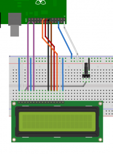
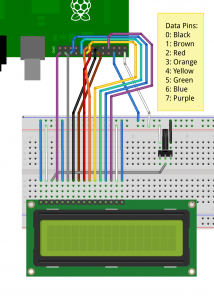
In the above Fritzing diagrams, the 4-bit one would be initialised by:
fd = lcdInit (2, 16, 4, 11,10 , 0,1,2,3,0,0,0,0) ;
and the 8-bit one by:
fd = lcdInit (2, 16, 8, 11,10 , 0,1,2,3,4,5,6,7) ;
- lcdHome (int handle)
- lcdClear (int handle)
These home the cursor and clear the screen respectively.
- lcdPosition (int handle, int x, int y)
Set the position of the cursor for subsequent text entry.
- lcdPutchar (int handle, uint8_t data)
- lcdPuts (int handle, char *string)
- lcdPrintf (int handle, char *message, …)
These output a single ASCII character, a string or a formatted string using the usual printf formatting commands.
At the moment, there is no input cursor control and no clever scrolling or wrapping of data sent to the display. It is up to your program to manage the display as it needs to.
Do see an example program in the examples directory inside the wiringPi software distribution.
Connecting them up:
Connecting up displays is relatively straight forward. You pick 4 or 8 GPIO pins for the data bus, then 2 more pins for the control. The LCDs have 2 control wires labeled RS and E. the E pin is what we refer to as the strobe pin above.
The R/W pin on the LCD must be connected to 0V/Ground and this is vitally important if you are using a 5V display.
You refer to the diagram of the edge connector on the LCD and use that to hook up the pins on the GPIO connector. Use the diagram here to help you keep track of the GPIO pins you are using.
Note the pin numbers on the GPIO connecting (using either wiringPi pin numbering or GPIO pin numbering) and enter those into the lcdInit() function call and you must call wiringPiSetup() or wiringPiSetupGpio() before you use this library.
For a 2nd (or 3rd, etc.) display, you wire the displays in parallel, connecting up all the same pins with the exception of the E pin. Each display needs its own unique E pin connected back to a different GPIO pin.


