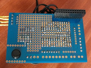
As part of my Big Trak refurbishment (not going as well as I wanted it to), I decided to use the Adafruit Prototyping Pi Plate to mount the additional electronics on. If you’re not familiar with it, then this is it:

Adafruit Prototyping Pi Plate
So it’s a double-sided PCB with a GPIO connector tracked to various pads round the outside of the board with space to solder in headers or screw-terminals (or both!), as well as having space in the middle to solder components to, supporting a standard DIL type layout, SOIC chip mounting pads and an open area.
An interesting feature is that it extends the GPIO pins through the board, giving the possibility for stacking – almost like an Arduino shield…
So for the Pi Trak, what I needed to do:
- Power supply. Powering the Pi off batteries, I needed a regulator to feed a stable 5V supply into the Pi.
- A motor controller. Essentially a dual H-bridge controller of some sort.
- Interface from a wheel position sensor of some sort.
- Interface to the keypad.
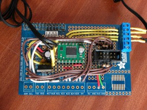
As I was running out of time to produce a prototype, I used a handy 7805 type regulator. This is great, but not too efficient – ie. it gets a bit hot when fed from 9v.
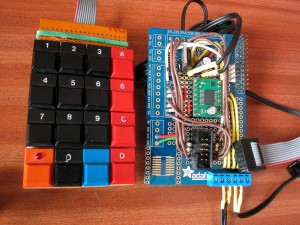
The keypad was originally going to be the Big Traks own keypad, but I substituted one I’d made earlier (some 25 years ago!) – it’s a simple 4×4 matrix and you can see 4 resistors on the protoboard. There is a 5th next to them which acts as a limiter for the LED that’s on one of the switches.
For the motor controller, I used the Pololu TB6612FNG unit which I bought locally via SKPang. (The Adafruit parts were supplied directly from the US, but note than SKPang now stock Adafruit components on the UK!)
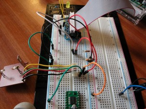
The wheel position sensor was an interesting one – initially I thought I could use a Lego sensor (since the rest of the thing was going to be made out of Lego by that point), however it turns out the Lego rotation sensor is analog – and outputs 4 different voltages depending on the angle… So a Plan B was hatched and I re-cycled the sensor from the original Big Track – seen here under test using the Adafruit Cobler board:
The wheel rotation sensor is the board to the left – it’s nothing more than an infra-red LED pointing to an IR photo diode. With a suitable current limiting resistor on the LED, the photo diode can be connected directly to one of the Pi’s GPIO inputs.
I also used to to test the motor driver too. I was a very easy way to do some “rapid prototyping” before committing to solder!
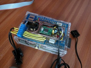
The end results was this:
This was the first time I’d used a board like this – more often I’d build projects on a re-usable breadboard, or on stripboard, so it did pose a few issues which I’d never encountered – The DIL area where I mounted the voltage regulator and the motor controller seemed fairly straightforwards, but with hindsight, I’d have made some of the links to the +3.3v and 0v supplies under the motor controller! In the open area, I cheated and just bent the wires of the components over to touch the pins of the 8-way socket I’d soldered on. Is that cheating, or is it the way everyone else does it? (Sensible answers please!)
However, overall, the board was very easy to work with – and does look a lot more professional than just hacking together some stripboard, and combine the board with the Adafruit case as I’ve done here, and it does open up many more possibilities for Pi interfacing projects.
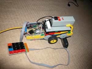
Finally:
This is the Mk1 Lego PiTrak. Much room for improvement and I need to mount the keypad on it – also want to put on an LCD display, so watch this space as they say…

