Hot on the heels of the PiFace, to add to my collection of Raspberry Pi interface boards comes the Mini PiIO Protoboard from DTRONIXS.
Photos
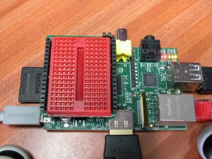
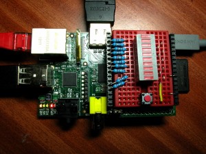
Top photo is the base board sitting on a Raspberry Pi, the 2nd one is the board made up with a minature version of my Ladder game.
First impression
It’s tiny!
It sits directly on-top of the Pi on the GPIO connector. The other end is sort of floating in space and like the PiFace, I’d strongly suggest putting some sticky-backed foam or felt pads to stop the board shorting out anything on the Pi (Which it did once when I was building this project on it, fortunately only rebooting the Pi…)
Kit and Assembly
It came as a kit of parts, PCB, GPIO connector, the 2 long edge connectors, a short 5-pin connector and some surface mount components to make up an independent 3.3v regulator fed off the Pi’s 3.3v supply.
Assembly was strightforward, although I did solder on the additional 5-pin connector, then realised nothing actually connects to it, and it stops the little breadboard from fitting, so had to unsolder and remove it.
The long pins down each side carry almost identical signals… Starting at the end furthest away from the GPIO connector, there is 5v, 0v, GPIO pins 17, 18, 21, 22, 23, 24, 25 and 4, then 0v and 3.3v. After that the 2 sides are different – the side nearest the edge (SD card) carrys the serial and I2C port pins and the opposite side carries the 5 SPI interface pins.
One thing I really like about the board is that the GPIO pins are actually labelled 0 through 7 – and they correspond directly with the wiringPi pin numbering scheme!
The 3v connections can be jumpered to come from the on-board regulator or the Pi’s own 3.3v supply.
And a little note about putting the breadboard on – it comes with a sticky-back, but if you are careful, then you can align the holes in the bradboard with the edge connectors, then it’s possible to plug in some DIL chips directly into the GPIO pins which may save a little bit of wiring.
Using it
As a quick experiment, I assembled a miniature version of my ladder gameusing a 10-segment LED bargraph display chip and assembly was quick and straight forward – the original used 12 LEDS but I only had 10 LEDs in a convenient package, so had to modify the program a little.
Conclusion
So if your after something to help you quickly get a few LEDs and switches going, or to experiment with a single DIL chip interface, then this little board is certainly one to look out for! It makes the main 8 GPIO signals easily avalable on both sides of the board with power and ground on both sides too which can make wiring signals to either side relatively easy.
The separate 3.3v regulator can be used to take some of the load off the Pi’s 3.3v supply – probably essential if driving something that’s going to take more than a few 10’s of mA.
Other than putting some sort of isolation between it and the Pi, the only minor issue I have with it is that like the PiFace board, it won’t fit into the SKPang cases I’m using although I’m pretty sure I could modify the pillars on the SKPang cases to take one, other than that it’ll very probably be the first protoboard I’ll reach for when trying out something small.


