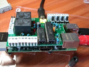
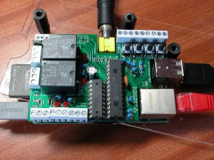
PiFace is a peripheral IO device for the Raspberry Pi. It was announced at the recent Cambridge Raspberry Jam event so I bought one for the princely sum of £30.
It’s designed to fit on-top of the Pi and has an identical footprint with cut-outs to accommodate the Composite video, Ethernet and USB ports. It takes 3.3v and (optionally) 5v from the Pi itself, although there is provision for a separate supply to power the output relays and buffers. While the driver chips will support up to 20V, the relays are designed to only run at 5V, so the external supply needs to be 5v. My board was not fitted with this socket.
Photos
These photos show the PiFace fitted to a Raspberry Pi. The 9 screw terminals at the bottom/front of the photos are the output pins (Power is the pin on the left), the 2 sets of 3-way screw terminals are the relay outputs and the set of 9 at the top/back are the inputs with 0v being the one on the left, closest to the composite video output.
The PiFace leaves all ports accessible on the Raspberry Pi itself, with the obvious exception of the GPIO port. It uses power and the SPI bus on the GPIO only. It does not make the other GPIO pins available for use.
2 of the outputs are connected to relays which are capable of switching 10amps and 230volts… That’s a 2Kw load however I would not personally like to try to switch anything close to that with those little screw terminals.
Fitting
The PiFace itself is supported only by the large capacitor on the Raspberry Pi board as well as the GPIO connector. If you were to exert a little too much force on the PiFace, it’s possible you may damage the capacitor and also short circuit some of the PiFace’s pins on the HDMI connector. One of those sticky felt pads on the PiFace at the location of the HDMI connector is helpful.
It’s probably not recommended anyway, but do not try to fit the PiFace to your Raspberry Pi when the Pi is turned on – they do it in one of the videos but it caused my Pi to reboot – presumably due to a power spike going through the board.
What You Get
PiFace gives you 8 buffered input pins (with 4 switches on-board connected to 4 of these pins), and 8 buffered output connections. 2 of the output connections are connected to mechanical relays.
You can use the 2 buffered outputs in parallel with the relays, but they will obviously click on/off when you use them. The relay outputs have an LED wired in parallel with the relays and there are 2 other LEDs on the output pins, so with the 4 buttons and 4 LEDs (with the relays clicking away), it’s possible to do some very simple experiments right away.
GPIO
The GPIO is handled by an MCP23S17 SPI/GPIO interface chip. This provides 16 general purpose IO pins with the PiFace dividing them into 8 inputs and 8 outputs.
The Input pins have a 330Ω series resistor and the MCP23S17 is capable of applying internal pull-up resistors making it easy to detect signals that pull to ground such as simple switches without any additional components.
NOTE: Like the GPIO on the Raspberry Pi, the MCP23S17 is a 3.3v chip. Do not attempt to connect it to systems generating more than 3.3v outputs.
The outputs are driven via a standard ULN2803A darlington driver chip.
There is no support for the interrupt capability of the MCP23S17 although this could be achieved by soldering a wire from its interrupt output pins to 2 of the Raspberry Pi’s GPIO pins.
Software
There isn’t any 🙁
At least none that I could find, other than references to a new SPI driver for the kernel, and as I’m using one of Chris Boot’s kernels with his SPI driver installed, (which I think is now back-ported to the official kernel released by the foundation), so I didn’t think there was much point pursuing that line of attack… So armed with the circuit diagram, the MCP23S17 data sheet and some time, I wrote a version of wiringPi to work with the PiFace board. Details here including a software library and demonstration program.
Conclusion
It’s a nice little board. Relatively easy to use, but with no software supplied, could be quite daunting to use! Hopefully someone will produce and publish a Python, scratch, etc. libraries to enable it to be used easily, but until then, there’s wiringPiFace.
I’m somewhat disappointed that there is no way to disable the 2 on-board relays. I wanted to drive 8 LEDs and detect a switch with it to hopefully use it to drive a copy of Mike Cooks Magic Wand the buzzing from the relays is too much to bear and I really don’t want to un-soldering them, so a couple of jumpers would be handy on the next revision…
I feel that the inputs could have been handled better – especially for something intended for classroom use – with e.g. opto-isolators to allow for a range of input voltages from 3 to 12v for example. That would make it much more robust and versatile in a classroom environment… Probably add to the cost, and possibly board size too though, so I can see where a compromise may have been made, however the MCP23S17 is socketed and replacements cost under £1 in the UK.
Also, the circuit diagram shows 2 jumpers that are not fitted to my board – they are attached to the chips address-select lines. The manual for the MCP23S17 says that these pins must be strapped either way, even if they are not being used, so I soldered on some 0.1″ headers and put on a couple of jumpers. I’m hoping this is just an oversight on my early production board… It’s also hard-wired to the Raspberry Pi’s first SPI chip select output – again, a jumper would have been nice, but given that you can’t connect anything else to the Pi when this is connected it’s probably a moot point.
And the inability to connect anything else to the Raspberry Pi’s GPIO connector is somewhat frustrating. I can’t use the PWM output, can’t use the serial port, can’t use the I2C port, nor can I use any of the other GPIO ports that the Pi provides. Maybe one day we’ll see some sort of stacking “shield” arrangement like Arduinos have, however…
The mounting is a little flimsy, I’d like to see a proper spacer pillar in the underside of the board, just to stop it wobbling, although even a sticky-backed felt pad over the HDMI port would be a good start.
I feel it is much less capable than the Gertboard, but at the same time it’s also much simpler and might just be the thing to enable some easy control applications for demos, and even with the 2 relays the ability to drive some low-voltage motors – that combined with its size might just make it a good little board for a floor-crawler robot of some kind. A control board for my PiTrack project? Now there’s a thought…


