
The Gigatron is a TTL computer and when I first heard about it, I thought that with that name, I had to get one…
The Gigatron
… and there it is. https://gigatron.io/
So what is it?
It’s the brainchild of Marcel van Kervinck and Walter Belgers.
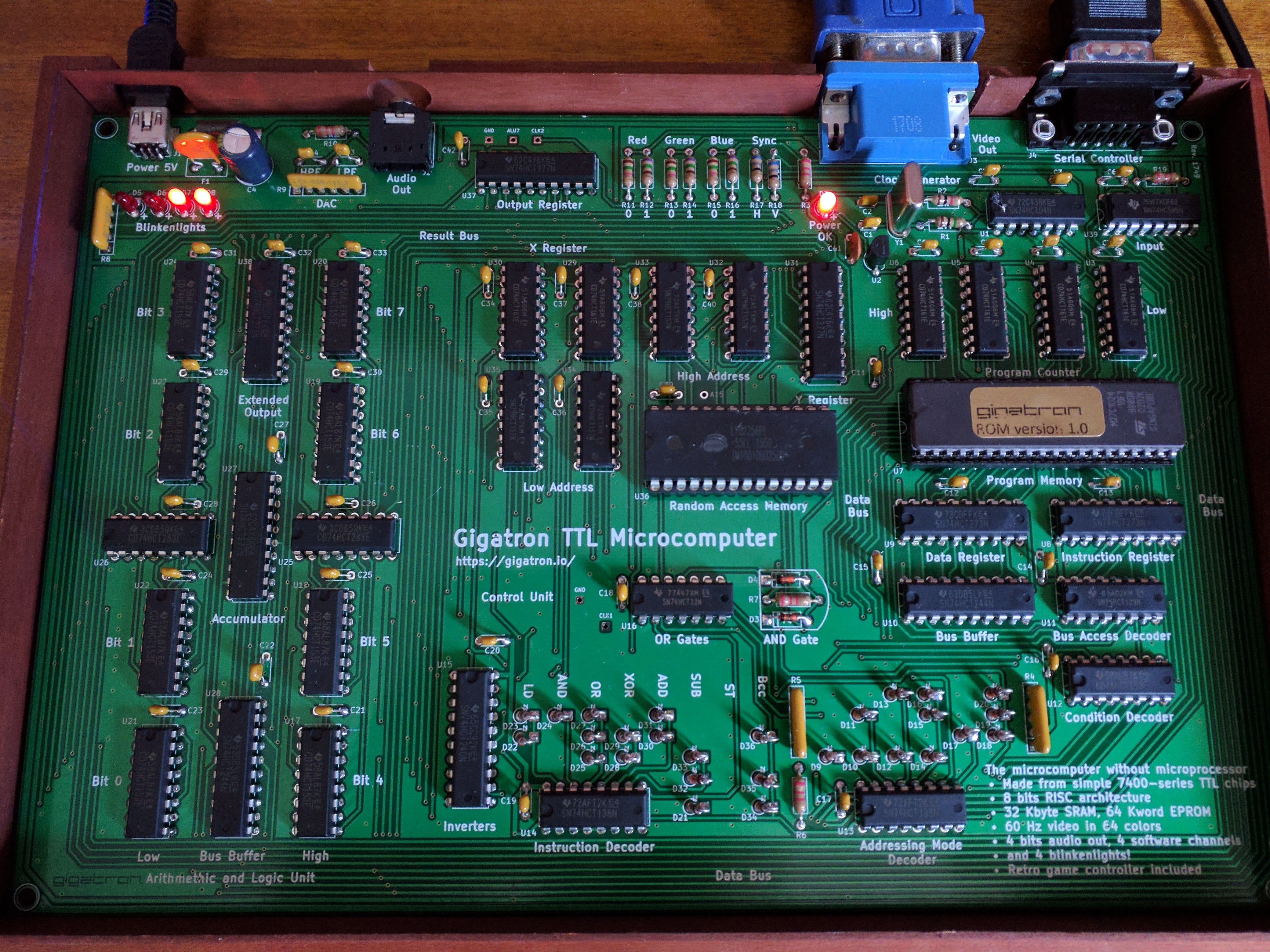
In essence, it’s an 8-bit computer (I’d struggle to say “micro” here as it’s not that small!) made almost entirely from TTL chips with a few discrete components thrown in for good measure. It has a reduced instruction set of just 8 instructions with 32KB of RAM and 64KW EEPROM (16-bit wide EEPROM, so 128KW of EEPROM in total) It comes in a very nice case with a game controller and sockets for power in (mini USB), 3.5mm audio jack output and VGA for colour video output. The game controller is a clone of the Nintendo Famicom controller.
TTL?
TTL is Transistor-Transistor Logic. Essentially it’s a way to encapsulate many transistors into a single integrated circuit, or IC. The ICs are typically digital in nature and featured simple logic gates – AND/OR, etc. to more complex shift registers, latches and so on. The technology dates back to the early 1960’s but wasn’t standardised until Texas Instruments created their line of 74xx ICs in about 1966. Until then computers and other digital devices were made up from discrete components, transistors, diodes, resistors, etc. on large (or small) circuit boards. These new ICs allowed increased transistor density and lower power consumption.
The idea of making a computer of out of TTL is not new. DEC created the PDP-8/i computer in 1968 which was a successor to their PDP-8 computer (c1965) and was the first one they made almost entirely from TTL chips – the ‘i’ in PDP-8/i means Integrated Circuits.
And there are similarities between the Gigatron and the PDP-8 – I suspect Marcel and Walter are both PDP-8 enthusiasts in some way…
It’s a kit
Gigatron is supplied as a self-solder kit. I think it’s the biggest self-solder kit I’ve had in a very long time – if ever. However the (real, printed and bound) instruction manual is one of the best I’ve seen. Colour pictures and step by step instructions. Being a veteran solderer I assembled it in a slightly different order, but the supplied instructions do take you through some trouble shooting and tests along the way which for novice solderers will add confidence when you get going. Doing the multimeter checks and early power checks will be very worthwhile if you’re relatively new to this. (Also if you’re not – I’m a real fan of incremental testing rather than build a huge thing then try to debug it) The only thing I’d add to the instructions would be to get yourself a big lump of blue tack or something similar – I prefer using that to keep components on the PCB when turning it over to bending the leads out.
No Sockets?
The RAM and EEPROM chips are in sockets – the TTL chips not. Is this a big deal? I don’t think so. The anti-static foam sheet that all the chips come on is populated with the chips in the right locations and the right way round, however you should still check before putting a chip in and soldering it in. It is possible to de-solder and extract a TTL chip, but my experience is that it’s easier to simply snip the legs off, take the pins out one by one then solder in a new one – which is fine if you have spares, so just take your time and you shouldn’t have any issues.
Architecture
The native instruction set is very RISC at just 8 instructions with a handful of addressing modes. It’s an 8-bit Harvard architecture machine with effectively five separate data paths, one of which is the ROM where the code lives and that’s a 16-bit data bus. Instructions are effectively 16-bits wide – one byte is the instruction (which is 3 bits for the instruction, 3 for the addressing mode and 2 to select the bus), and one byte for data. It features a single 8-bit accumulator and a 16-bit memory pointer register accessible as 2 x 8-bit registers, X and Y which allows for different addressing modes. The 16-bit instruction bus allows for operations like “load accumulator with an 8-bit value” to execute in one cycle. However for the most part you are not expected to write in this low-level code, but to write in code which they have designed as a virtual 16-bit CPU (vCPU) which comes with a high (ish) level compiled language to go with it.
So here you have a 3-level system – the native code which is almost like a microcode in todays terms, the virtual CPU (vCPU) interpreter which is written in the native code and the high level language; GCL – Gigatron Control Language. GCL runs from RAM.
Programming directly in the native micro code is possible, however, it’s a tightly constrained system as it is not just the code for your programs, but is also controlling the video and audio output and other IO such as the game controller and “blinkenlights”. This all happens behind the scenes as it were when you write programs in the vCPU or GCL codes. Also – the native micro code can only run from ROM.
Video Output
The video is a VGA standard output with a 6.25Mhz dot-clock. 6.25 Mhz is also the clock frequency of the processor, so the video is generated one instruction at a time which fetches a byte from RAM and sends it to the 6-bit colour DAC to generate 64 colours per pixel at a QQVGA resolution of 160 pixels by 120 lines. It’s a simple RGB encoding; 2 bits of red, 2 green and 2 blue. There are some hardware optimisations/trade-offs here though – essentially it’s an 8-bit output latch which uses 6 bits for the colour and 2 bits for the H and V sync signals. To use all 8 bits for colour would require an additional output latch to drive the video sync signals.
Generating that in software uses almost all the processing power of the cpu, but there are free cycles at the end of each line during the horizontal sync period and at the end of each frame during the vertical sync period, however to make things a little easier for user programs the system skips every 4th line and that time is used to run GCL programs. You can turn off the line skipping though – the system still works, just slower.
The video system is somewhat wasteful of memory – you lose 2 bits per byte and to optimise the lines, they are arranged in RAM as 120 lines of 160 bytes each, however hose lines are aligned to a 256 byte boundary, leaving 96 bytes per line unused. It is possible to load code or data there though.
Sound and Blinkenlights
The sound system is again driven by software. There is an 8-bit latch which is split into 2 x 4-bit outputs. 4 bits for the LEDs and 4 for the DAC and audio output filter. Sound tables are held in RAM and the micro code mixes 4 channels of sound into one to send to the hardware at fixed intervals. I’m not sure if it’s possible to change the LEDs from user code though – will need to investigate further.
Software
The system comes with a 128KB EEPROM which contains the micro coded “operating system” (which is the drivers for the video, game controller, LEDs and sound), the vCPU interpreter and a selection of GCL coded programs – Classic Snake game and a racer program very much like one I played on the Apple II some 40 years ago… There is also a Mandelbrot program and some static images.
Writing your own
You can write your own code for the Gigatron, however as I type this, it’s somewhat tricky. Marcel and Walter are working on some development tools to make it easier, however following some hints I have been able to write a simple GCL program and make it run on the Gigatron. This involves pretending to write a ROM module, building the ROM, extracting the vCPU bytes for your module into a C language program – burning this program into an Arduino which is connected to the game port, then booting the Arduino – it then pretends to be a game controller to the Gigatron, enters the Loader application, then uses the game port to send the bytes of your program into the RAM of the Gigatron then starts it going. It’s not an easy process, but usable for now.
My first Gigatron program is simply a screen clear:
{
  Gigatron code to do some simple screen clearing
  -Gordon Henderson <projects@drogon.net>
}

gcl0x

0 c=

[do

{ Clear line at a time, top to bottom }

$0800 p= q=

120 l=

[do
  160 w=

  [do
    c q.
    q 1+ q=
    w 1- w=
  if>0loop]

  256 p+ p= q=

  l 1- l=
if>0loop]

c 1+ c=

{ clear column at a time, left to right }

$0800 p= q=

160 w=
[do

  [do
    c q.
    $100 q+ q=
  if>=0loop]

  p 1+ p= q=

  w 1- w=
if>0loop]

c 1+ c=

loop]
So there you have it. Right now it’s a very nice toy, if a little expensive at €160 (Currently €149.50 for early adopters) It does have a lot of potential though especially if, like me, you like esoteric little systems.
If you want to know more, hop over to their site: https://gigatron.io/