If you’re a reader of the MagPi magazine then you may have seen my Halloween Pi project in the October issue…
If not, then have a quick wander over to their site: http://www.themagpi.com/ and have a look!
Octobers magazine featured a little Halloween project I did – sadly, due to a few factors beyond my control – some family illness necessitating a round trip of some 5000 miles to Tenerife and back, and the seasonal availability (or rather lack or it!) meaning I was little pushed for time and unable to get a real pumpkin before the publication date, I felt I didn’t give it all it was worth, so I’m re-doing it here for my own archival use and to maybe add a few more things into it.
The idea was to put some flashing LEDs inside a pumpkin along with a PIR sensor so that when triggered by movement, the LEDs would flash some colourful patterns.
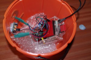
Because I couldn’t get a real one on-time, my pumpkin was built in a plastic bucket… Not that bad really, but could have been better – it was in the shape of a Halloween pumpkin though!
Photos
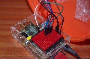
Rather than solder, I used some heat-shrink to hold the wires of the LED to the female to male patch leads. The little board on-top of the Pi is the Dtronixs Minipiio board and it’s all sitting inside an Adafruit case.
The rest of the hardware if fairly straightforward – They are common cathode RGB LEDs and the PIR sensor.
Ingredients
- RGB LEDs
- PIR Sensor
- Standard Breadboard
- Dtronixs Minipiio board
- Patch leads
- Adafruit case (UK)
- Resistors – 2 x 150Ω for the Red LED, 4 x 100Ω for the Blue and Green elements.
- As well as a large pumpkin!
The Dtronixs board isn’t available – yet, but I understand “real soon now”…
If you’re outside the UK/Europe, then I strongly suggest looking at the Adafruit site for these bits & pieces, and more, but most hobby electronics shops should have everything you need.
Note that the resistors are a little lower than I’d normally use – these RGB LEDs are quite bright and need a slightly higher drive requirement than the common red/green/yellow ones to be effective. (and even here, those are the typical values for a 5v supply – the LED will be slightly dimmer powered from the Pi’s 3.3v, but you really won’t notice it)
Wiring it up
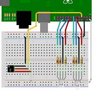
No surprises here – GPIO’s 0, 1 and 2 (wiringPi numbering convention) to the Red, Green and Blue of the first LED, 3, 4 and 5 to the RGB of the 2nd LED, and pin 7 to the input from the PIR sensor. A Fritzing diagram is below:
The first LED is on the right in this diagram. (Not that it really matters!)
Software
I wanted to use the software PWM library in wiringPi to light the LEDs up and make some interesting colours/patterns, so that meant the software needed to be written in C (at least initially)
If you don’t already have the wiringPi library and gpio utility installed, then:
cd
git clone git://git.drogon.net/wiringPi
cd wiringPi
./build
and that will get the code and install it for you.
Get the Halloween software by a similar method:
cd
git clone git://git.drogon.net/halloweenPi
cd halloween
make
Before running the software, you can test the LEDs and sensor with the following commands:
for led in 0 1 2 3 4 5; do gpio mode $led out ; done
gpio mode 7 in
gpio write 0 1   # 1st Red LED ought to be on
gpio write 0 0 ; gpio write 1 1 # Red off, Green on
gpio write 1 0 ; gpio write 2 1 # Green off, Blue on
You can do the same for the 2nd LED using numbers 3, 4 and 5 respectively.
If you’ve wired the colours up wrongly, then it’s easy to change them and use the gpio command to check.
The PIR sensor works by firstly sampling the surrounding heat “signature” for a few seconds, then waiting for it to change. So to test it, you need to be very still… and keep on typing the following command: (Use the up-arrow key!)
gpio read 7
It should read 0 when not triggered and read 1 when it is triggered.
At this point, assuming all is OK, you can run the program:
sudo ./halloween
and see what happens. Remember that it needs 5 seconds of stillness to register, then you can move and see what happens.
If you want to change the patterns then you need to look at the ledPatterns.c file. You can use that as a template, or modify the code already there – whatever you do, have fun!
Extras
If you are carving a real pumpkin, then here is a suggestion or 2 – get a black marker pen and draw a zig-zag round the top, also decide where the back is and draw a short vertical line through the zig-zag – that way, you’ll know exactly where the top goes when you come to putting it back on again!
Scoop out the flesh, but don’t throw it away! You can use it to make some tasty roast pumpkin soup as follows:
Put the flesh into an ovenproof dish with a glug of olive oil and a sprinkling of salt and roast in a hot oven – 220C or Gas mark 7 for about half an hour or until it starts to take a little colour.
Remove from the oven and transfer into a pan. Add in half a vegetable stock cube (or a whole one if you carved a huge pumpkin!) and a small tub of single cream. (again, maybe a a large pot if it’s a huge pumpkin!)
Mash or blitz with one of those hand-held mixer thing and return to the heat to thoroughly warm through – add a little milk or water if it’s a bit thick, and serve immediately with some fresh crusty bread.
For a little variation and more texture, add in a drained tin of sweetcorn and to make it a little warmer, try some smoked paprika sprinkled on-top when serving.
Some Halloween information
Halloween is an old festival or celebration, or ritual which has been adopted by many cultures and religions over the world. It’s roots may originate in acknowledging the autumn is ending and we should take stock for winter, or to remember the passing of souls, or a time to hide from ghouls or the souls of enemies (hence the masks and lanterns!) For us, it’ll be a bit of fun, some hot soup and a fancy Raspberry Pi powered lantern!
In Scotland (Where I’m from), you should traditionally use a large yellow neep and make a “tumshie heed”. Some English counties may traditionally use a mangelwurzel and if you can get of suitable size that may be appropriate.
The modern trandition of “trick or treat” may originate from an early Christian practice of baking small round cakes for All Saints Day (November 1st)


