Part 1: The Hardware & Driver
Some time back, I joked that the Raspberry Pi’s GPIO port really stood for Game Port IO… So to make that joke come true, I present a way of interfacing the NES Joysticks to the Raspberry Pi.
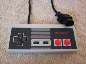
First you need the joystick/controller unit, and a quick trip to the Plymouth Market where I’d had a tip that there was a stall selling retro gaming gear and I returned with a pair of them for under a tenner. Bargain!
Note the weird 7-pin connector. You can buy sockets for this off eBay and if you currently own an old console, then you may wish to pursue this approach, but as I don’t own a console (and am unlikely to ever own one!) I decided to chop the connector off…
(Yes, sorry – if you’re a retro gaming enthusiast, I know you can now buy matching sockets for them, but I really didn’t want to go to the added expense, and I did leave a long enough tail on the plug so that I could re-connect it should I ever have the need…)
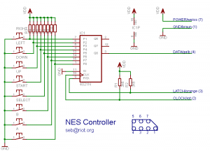
Inside, I found 5 wires… 5 wires and 8 buttons. Curious, but some googling later and I found this diagram:
Many thanks to Seb for letting me post it here.
And if you don’t read German, the colours on the diagram are (from the top down), White, Brown, Yellow, Orange and Red.
So what’s inside is a 4021N CMOS shift register. This has the task of sampling 8 buttons and then makes the data available via a serial interface controlled by 2 pins – a latch and a clock. The way it’s wired up requires one latch pulse and 7 clock pulses to get all 8 data bits out, but this is easily accomplished in software.
Some wire trimming, soldering and heat shrinking later and I end up with a pair of joysticks with pins on the ends:
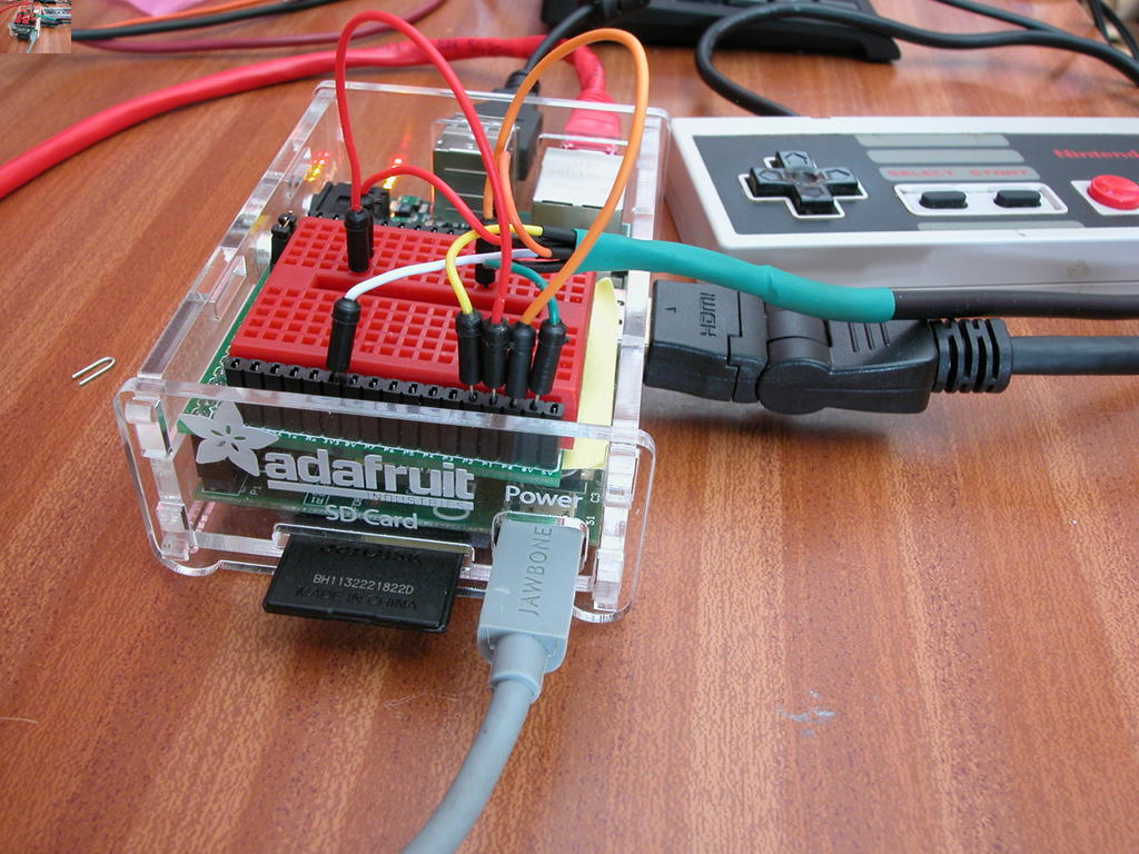
I took 5 short male/male breadboard patch leads, chopped them in half and soldered & heat-shrunk them on. I’d no brown patch leads, so I used green here. I’m using an Adafruit Cobler breakout just because it was next to me and already plugged into a Pi, but when I first developed it, I used the cute little Piio protoboard from DTRONIXS:

NES Controller on a Mini Piio Protoboard
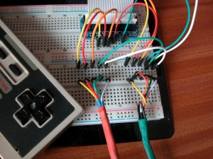
So you have plenty of options for hooking them up…
You could even make some sort of plug & socket arrangement and I may do just that in the near future too… The thing to note is that you have to split power (3.3v) to go to both controllers, then separate the 3 data/clock/latch pins…
In-theory the Pi can drive 5 Joysticks without any issues and I suspect (but haven’t tested it yet) that you can double up on the either the latch or clock pin, so 3 pins for the first controller, then 2 pins for each subsequent one, giving the possibility of connecting up 8 joysticks if you were really inclined to do so!
So I’ve catered for up to 8 joysticks in my driver code and made the code part of the wiringPi library. (It needs wiringPi to drive the GPIO pins anyway) The library is simple enough – firstly initialise wiringPi in either native pins mode, or GPIO mode (You can use Sys mode, but it’s really quite slow!), then call the NES controller setup code to tell it what pins to use, then you can read the controller. So:
#include <wiringPi.h>
#include <piNes.h>
...
 if (wiringPiSetupGpio () < 0)
  {
    fprintf (stderr, "Can't setup GPIO: %s\n", strerror (errno)) ;
    exit (1) ;
  }

// Data on pin 21, Clock on pin 18, Latch on pin 17
//    (BCM_GPIO pin numbers)

  if ((joystick = setupNesJoystick (21, 18, 17)) == -1)
  {
    fprintf (stderr, "Unable to setup joystick\n") ;
    return 1 ;
  }

  buttons = readNesJoystick (joystick) ;
  if ((buttons & NES_UP) != 0)
    // The Up button is being pushed
Do see the nes.c program in the examples directory and refer to the piNes.h file for the defined constants for each button. It is possible to read simultaneous multiple button pushes – the return from readNesJoystick is an 8-bit value with one bit set per button.
Now we have joysticks, we need a game, and to get something going quickly I used my BASIC and wrote a simple game of Pong (aka Tennis) which I’ll describe tomorrow!


