
The Gertboard has 6 outputs that are driven from a ULN2803 darlington driver chip. This is an open-collector output and is capable of sinking a maximum of 500mA in total. You can connect the outputs to a higher voltage than the normal 3.3v that the Pi uses – Up to 50v if required! (Although I’d suggest you stick to something lower…)
Note that all devices you connect to it should share the same common voltage supply. (They’re all wired together on the Gertboard)
To demonstrate, I’ve wired up a 6-digit, 7-segment common cathode display.
There are several strategies for connecting up multiplexed 7-segment displays. One way (and one I did some time back for a project post) is to use one resistor per digit on the common wire. The advantage is that it’s a very minimal approach, and cost effective – the downside is that the software is slightly more complex and you can only light one segment on one digit at any one time. This means that for 4 digits of 7 segments, you need to potentially light up 4 * 7 = 28 LEDs, one after the other and do this quick enough to have no noticeable flicker.
The way we are doing it for this demonstration is to move the resistors to each segment, so we can light up all 7 at once (if needed!) The down side is that there is then potentially 7 LEDs worth of current going through the common pin – and with the display I’m using that’s potentially 200mA – this is far more than what a single logic pin can manage – so it’s an ideal task for the higher current darlington driver.
Below is a Fritzing diagram of a single digit on a breadboard:
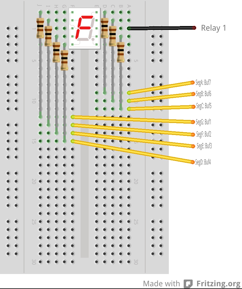 You’ll have to imagine 6 of these digits connected together – think of them all stacked on-top of each other, but the common connection brought out separately, but the 7-segments all connected together. The “Relay 1” label in the image connects to the corresponding pin on the Gertboard, not to any real relay.
So to illuminate a single digit, we output the pattern to its 7 segments, then take the common low for a period of time, then take it high again, and move into the next digit.
The software is relatively straightforwards and can be found as 7segments.c in the Gertboard directory.
Picture of it in operation:
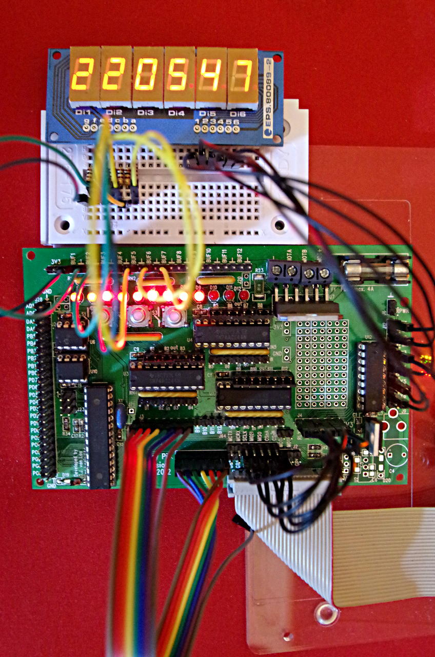 You can see that the 6 digit commons are wired over to the 6 “relay” outputs on the ULN2803 and the 7 segments are wired to the first 7 buffered outputs from the Pi through the Gertboard.
The display is reading 220547 – which was the time when I took the photo (22:05 and 47 seconds)
Sumary
The ULN2803 is an open-collector drive chip with 8 drivers inside although only 6 are available on the Gertboard. It can sink up to 500mA in total – our application here only sinks a maximum of 200mA on any one driver at any time. It also has built-in diodes to enable it to drive inductive loads such as relays and solenoids and small motors.