
NOTE: 11/2/2013: WORK IN PROGRESS – Things liable to change!
These pages serve as a demonstration of using the Gertboard with the wiringPi library from the command-line, in C and BASIC. There are several pages in this series and I hope they might act as a tutorial and possibly even an aid to making sure your Gertboard is fully functional.
- I have one of the early self-assembly Gertboards, but this applies to the later ones that are pre-assembled from Farnell.
- All these examples were tested using the standard Raspbian Linux distribution for the Raspberry Pi. If you are using a different distribution, then you may need to make changes, however most should work as-is.
WiringPi
WiringPi is a set of C functions designed to make it easy for C and C++ programs to access the Raspberry Pi’s GPIO. There is also a utility program; gpio which you can use from the command-line to test simple GPIO operations.
- Get and install wiringPi. The instructions are here.
Jumpers
(The little plastic & metal ones, not the wolly ones!)
There are several jumpers on your Gertboard. You should be familiar with them from reading the manual, but I’ll describe some of them here.
The buffer Input/Output jumpers: There are 12 of these in 3 groups of 4, all adjacent to the 3 74×244 buffer chips.
- When a jumper is on the side of the chip nearest to the Raspberry Pi Connector, then the corresponding buffer is configured as an input from the “BufX” pin through the buffer IC in the Gertboard and and into the Pi.
- When it is in the opposite side, close to the LEDs and the “BufX” row of pins, then that buffer is configured an an output from the Pi through the buffer IC and to the LED and the “BufX” pin.
The jumper bridge block: This is a block which forms part of the row of GPIO pins that are available for connection from the Pi into the Gertboard. A number of these (7) have the facility to bridge directly to Gertboard peripherals. These are the 2 serial lines from the Pi to the ATmega and the 2 SPI buses from the Pi to the Gertboards A/D and D/A converter chips.
I would suggest leaving these removed for now – however we will use them later on, so keep them safe.
Getting started
The first thing we’ll do is set the jumpers for output and light up the first LED, after that we’ll move onto more complex examples.
Move the 12 In/Out jumpers to the output position (think out -> away from the Pi, so they go closest to the LEDs), then connect the Gertboard to your Pi and boot the Pi
- I do not recommend making this connection with the Pi turned on just in-case you put the cable on the wrong way, or off-by one pin, etc. Do check everything before turning it on.
One thing to note: The inputs to the buffers are high impedance – what this means in practical terms is that if you touch one of the pins on the Pi side, then the LEDs are likely to light up. Sometimes just waving your hand near them is enough. While this isn’t generally a problem, it’s something you should be aware of.
- Note: That may only apply to early Gertboards – I’m told the later ones have pull-down resistors added to stop this effect.
To light our first LED: Connect a jumper wire from the Pi’s connector marked GP17 to the pin marked B1 on the long row:
| J2 | <- Jumper Wire -> | J3 |
| GP17 | <–> | B1 |
Login to your Pi and enter these commands:
gpio mode 0 out
gpio write 0 1
This should switch the first LED on. (note than GP17 is the internal BCM_GPIO pin number 17 which corresponds to wiringPi pin 0) Then:
gpio write 0 0
should turn it off. If that works, then congratulations!
But if not… Then you first need to make sure it’s all wired up correctly and that the Gertboard is functioning correctly. The photo below is how it should be wired up to start with:
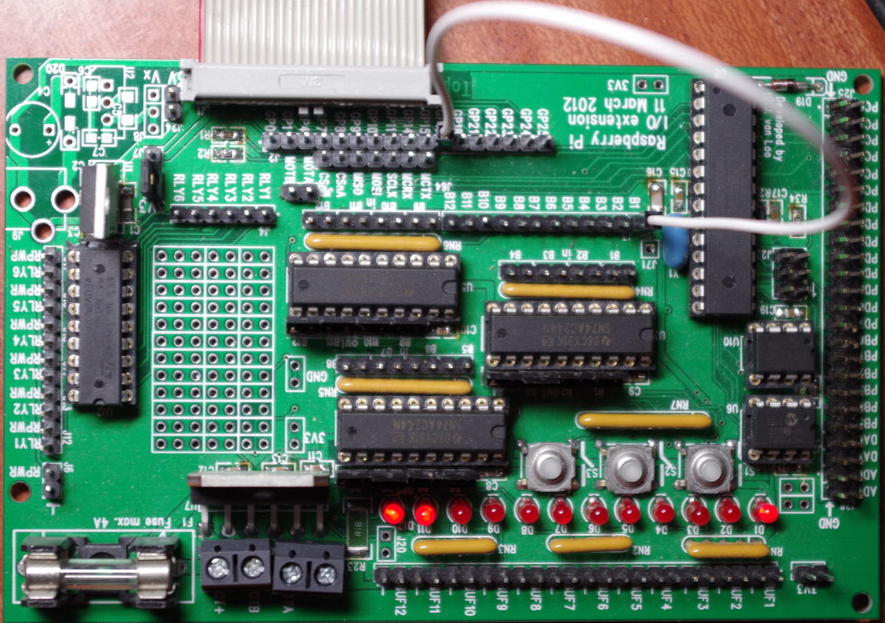 Check that you have it setup as above and try again. (Note that the LED on the right here – the first LED is lit, but also that the 2 LEDs on the left are also lit – this is simply due to the high impedance inputs floating high as mentioned above)
If you do get this far, then we can move onto the next step which is writing some programs using the Gertboard and wiringPi.
All the example programs here are part of the wiringPi software distribution, so if you have installed it correctly you shouldn’t need to do much typing!
Index to pages in this section
- Blink (Output to the LEDs, 1 then 8)
- Using all 12 LEDs
- Read the buttons
- Connecting things to the Gertboard
- Connecting to the higher current drivers
- Connecting and controlling a motor
- Looking at the on-board SPI devices
- Using the A/D (Analog to Digital) input
- Using the D/A (Digital to Analog) output
- Introduction to the ATmega