This is a game which I first encountered many years ago as a pure hardware project consisting of some discrete components, a 555 timer an analogue to digital converter, an LED bargraph driver IC, a dozen LEDs and a button. Actually, I don’t recall the exact components, but I recall the game… It was published in one of the many magazines at the time; either Everyday Electronics, Practical Electronics or Elektor Magazine. (If anyone else remembers it, please let me know!)
The idea is to climb out of a well using a ladder. There is a flashing LED representing your position on the ladder, but you can only move when the LED is on. If you push the button to try to move up when the LED is off, then you slide back down to the bottom again… The hard part is that the led flashes less and less the higher you get up the ladder, making it easier to keep the button pushed for too long when near the top, causing you to slide back down again. Additionally, if you don’t move by pushing the button then eventually you start to slide down anyway…
It’s a very simple game and was educational to build at the time, now to re-create it in hardware and software…
Simulating the circuit in software is in some-ways harder to do than to actually built the circuit in electronic components, but in can be used as an introduction to building up simple RC networks in a teaching environment.
To build the game, you’ll need almost all the bits in the SK Pang starter kit – 12 x LEDs, 12 x 270Ω resistors and one button. You can build it with less LEDs if you don’t have enough.
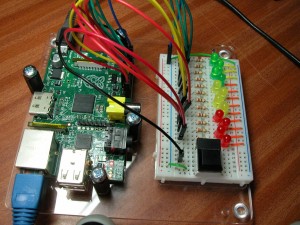
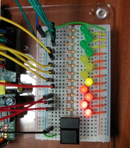
As you can see, I’ve changed the layout slightly from the way the Tux Crossing board was laid out. I’ve put the resistors on the other side of the LEDs and use short jumper wires to connect the LEDs to the 0v rail. The only reason for this was to make it look a little better to get the jumper wires away from the LEDs. I’ve also used a button out of my own bits & pieces box – The tiny buttons that come with the starter kit are OK, but I find them a little fiddly to use.
In these views you can see the layout a little clearer. the LEDs are staggered as they’re just a little too large to fit in a row, and they’re actually rotated thorough 45 degrees as the pin spacing is just a bit wide for the breadboard sockets. If you use 3mm LEDs you’ll probably be OK, but I only had 5mm LEDs to hand.
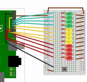
The board is wired up as follows – From top to bottom:
| LED | wiringPi Pin | GPIO Pin |
|---|---|---|
| 1 (Green) | 0 | 17 |
| 2 | 1 | 18 |
| 3 | 2 | 21 |
| 4 | 3 | 22 |
| 5 (Yellow) | 4 | 23 |
| 6 | 5 | 24 |
| 7 | 6 | 25 |
| 8 | 7 | 4 |
| 9 (Red) | 10 | 8 |
| 10 | 11 | 7 |
| 11 | 12 | 10 |
| 12 | 13 | 9 |
| Button | 8 | 0 |
Once built, you can use the gpio command and/or the following program to make sure all the connections are correct:
#!/bin/bash

setup ()
{
  echo Setup
  for i in 0 1 2 3 4 5 6 7 10 11 12 13 ; do gpio mode  $i out ; done
}

setup
while true; do
  for i in 0 1 2 3 4 5 6 7 10 11 12 13 ; do
    gpio write $i   0
    sleep 0.1
  done
  for i in 0 1 2 3 4 5 6 7 10 11 12 13 ; do
    gpio write $i   1
    sleep 0.1
  done
done
Copy this into a file – e.g. test.sh, then chmod +x test.sh ; ./test.sh
Test the button as before:
gpio mode 8 in
gpio read 8
Now that we have the hardware, we can have a look at the theory of operation, then finally the software.
Or check the video demo…
And if at first you don’t win, try again:


