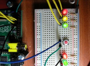
Our first GPIO example will start from the very basics and build up a UK Pelican Crossing simulator using 5 x LEDs (A Red, Yellow and Green and another Red and Green for the Red and Green “man” indicators), 5 x 270Ω resistors and a single push-button for the pedestrians to control the lights.
Here is a picture of the finished board, but we’ll build it up in stages as we go, and finally present some software to make it all work:
In the photo, all the LEDs are on. This was just to test the connections – it would not normally be like that when running the controlling program!
Video Demo:

