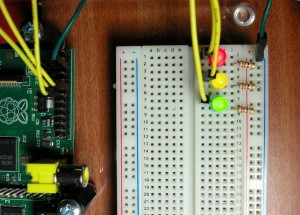
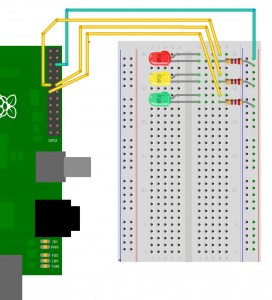
No surprises here – add 2 more LEDs to the board as shown below:
They are wired up as before with the Yellow LED being connected to wiringPi pin 1 (GPIO-18) and the Green LED on wiringPi pin 2 (GPIO-21)
Test with the gpio program as before. e.g.
gpio mode 0 out
gpio mode 1 out
gpio mode 2 out
gpio write 0 1
gpio write 1 1
gpio write 2 1
to turn the all on.
If you want to do this somewhat easier, then we can use the shell programming system:
for i in 0 1 2 ; do gpio mode $i out; done
for i in 0 1 2 ; do gpio write $i 1; done
for i in 0 1 2 ; do gpio write $i 0; done
to do this using the GPIO pins:
for i in 17 18 21 ; do gpio -g write $i 1; done
If the above doesn’t make sense to you, then don’t worry for now.
Lets move on to finishing setting up the breadboard in part 3.


