3: More LEDs and a Button

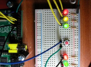
We’ll add 2 more LEDs and a button now and here is the final photo:

The Tux Crossing Board

The Tux Crossing Board

Tux Crossing

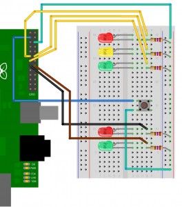
Finished Tux Crossing – Breadboard layout

So we now have a traffic light/pelican (Tux!) crossing simulator.

The 2nd Red LED is connected to wiringPi pin 3, (GPIO-22), and the 2nd Green LED is connected to wiringPi pin 4, (GPIO-23).

Test them as before with the gpio command, e.g.

for i in 0 1 2 3 4 ; do gpio mode $i out; done
for i in 0 1 2 3 4 ; do gpio write $i 1; done
for i in 0 1 2 3 4 ; do gpio write $i 0; done

The button is connected to wiringPi pin 8, (GPIO-0/SDA0), and the other side is connected to 0v. This pin has a 1.8KΩ resistor connecting it to +3.3v on the Raspberry Pi board. What this means is that when we set the pin to input mode and read the value, we are going to read in a logic high value (or 1 in our number terms), and when we push the button we connect the pin to 0v then the input will read a logic low value, or zero. This may appear to be the opposite way round to what we might expect, but we can easily cater for it in our programs.

Some designs for connecting buttons to the Rasberry Pi may include additional resistors, designed to protect the chips pin should you accidentally program it as an output. It’s not strictly necessary, but if you do program it as output, and write a high value to the pin, then you run the risk of damaging the pin, and possibly the chip.

We read the button as follows:

gpio mode 8 input
gpio read 8

The gpio program will print 1 or 0 depending on the state of the button. Expect it to print 1 when the button is not pressed, and print 0 when it is pressed.

To complete this we need to write some software to control it all

Comments

3: More LEDs and a Button — 38 Comments

  1. Just a short note…in my GPIO-command version (current download) i had to use “gpio mode 8 in” and not “gpio mode 8 input”. 🙂

  2. Thank you for this work, is very interesting to have tutorials to get started. There is a small error, which says: “The button is connected to pin 8 wiringPi (GPIO-0)” should read: “The button is connected to pin 8 wiringPi (SDA0).

    • Hi,
      Thanks. This is where confusion reigns in the world of GPIO. wiringPi pin 8 is GPIO pin 0 which is named SDA0.
      I’ve updated the page to read SDA0 though.
      -Gordon

  3. Hi,
    How can i “save” the value of a pushbutton? I’d like to make a push button who if i push one time a led turns ON and if i push a second time the led turns OFF. How can i get it work? Thank you!

    • Hi,

      wiringPi doesn’t provide that sort functionality directly, but it’s relatively easy to do in a program, so something like:


      ledState = 0 ;
      for (;;)
      {
      // Wait for button to be pushed
      while (digitalRead (BUTTON) == HIGH)
      delay (1) ;
      digitalWrite (LED, ledState) ;

      ledState ^= 1 ;

      // Wait for button to be released
      while (digitalRead (BUTTON != HIGH)
      delay (1) ;
      }

      should have the effect you want – the statement ledState ^= 1; applies an XOR function to the value of ledState, toggling it between 0 (off) and 1 (on)

      -Gordon

      • Thank you very much for the code. Could it be possible to write this code also in BASH? Because I need to write only in bash language.
        Anyway, amazing work!

        • This is not as efficient as it could be, but it does work (I’ve just tried it). It may miss a very brief push of the button though, but you can make the sleep time smaller to help catch that, at the expense of more cpu usage.


          #!/bin/bash

          # Pins = led wiringPi pin 0 is GPIO 17, button wiringPi pin 8 is GPIO pin 0
          # and that pin has a 1800 ohm pull-up resistor so will normally read high,
          # pushing the button will make it read low.
          led=0
          button=8

          gpio mode $led out
          gpio mode $button in

          # waitButton:
          # Wait for the button to be pressed. Because we have the GPIO
          # pin pulled high, we wait for it to go low to indicate a push.
          #######################################################################

          waitButton ()
          {
          echo -n "Waiting for button ... "
          while [ `gpio read $button` = 1 ]; do
          sleep 0.1
          done
          echo "Got it"
          }

          waitReleaseButton ()
          {
          echo -n "Waiting for button to be released ... "
          while [ `gpio read $button` = 0 ]; do
          sleep 0.1
          done
          echo "Got it"
          }

          # Start with the light off

          gpio write $led 0

          while true ; do
          waitButton
          gpio write $led 1
          waitReleaseButton

          waitButton
          gpio write $led 0
          waitReleaseButton
          done

          • Thank you very much!
            I understand , but i need to write a code that runs with the mcp23017 extender that uses a python command (for example $ ./mcp23017.py -b a -o 0 -s high) to switch high or low. Do I add some extra code for a code fully functional?

          • The mcp23017 is an I2C device that add on additional GPIO type functionality. wiringPi won’t drive this device as it stands. Later kenels do have I2C drivers in it though, but I don’t yet have any wiringPi examples that use I2C. It is something I’m looking into though.

            -Gordon

  4. Gordon,
    A minor point – you do not say how to connect the switch to 0V
    and the photo doesn’t help since you can’t see where the other end of the wire goes.
    Plus since the kit has male to female patch leads, you need to insert a spare bit of wire (off a clipped resistor) to make a male-male lead.

    Not a problem for me to figure it out but it might catch others out

    – Dan

    • Hi Dan,
      Yes – more documentation is needed and I’m working on that…. I have boxes of M/M jump leads, so it’s just too easy for me to pick one up and wire it in without thinking!
      Cheers,

      -Gordon

  5. I have stopped the buttonswitch from bouncing around with a little blutak to its base. Now to try to short out the switch. One side to RPi pin 3 and the other to the top row of the bb (0v).

  6. Hi Gordon,

    Thanks for providing the tutorial, it should come in handy when all my electronic parts arrive in the next few days. Just wanted to ask, theoretically how many LED’s could I have powered by the Pi – what concepts should I be looking at to progress beyond the 6 LED’s you have built here.

    Enjoying your site, itching to connect with the NES controller!

    • Well… In theory, there’s only about 50mA “spare” on the 3.3v supply, so that’s 5 LEDs at 10mA, however I have successfully driven 17 LEDs from the GPIO pins on the Pi… It’s probably slightly exceeding some limit somewhere, but I appear to be able to “get away” with it.

      Also, my “ladder” game uses 12 LEDs and that’s not had any issues at all.

      But if you wanted to power more/ or high power ones, then you can use the 5v supply (or an external supply!) and some buffer chips to drive them – e.g. uln2803 type drivers…

      -Gordon

    • I’m currently learning the “Fritzing” layout package, so will be updating everything when I can.

      However, there is no pull-down resistor on the bradboard. If it’s the switch, then the Pi has an on-board 1.8K pull-up resistor and the switch is connection the GPIO pin to ground.

      -Gordon

  7. hey gordon.

    the diagrams work like a charm.

    i just mis read the info before, i tought u placed a pull (up-down) resistor like u normaly do with logical inputs.
    and i was looking on the foto but got lost cuz i dint saw the resistor.

    but now i see the raspberry pi has them internal.

    anyway i ended up putting a pulldown resistor in it anyway and it still functioned so nothing bad 😛

    thanks for the effort grts paul

  8. Gordon, great example – managed to spend an afternoon getting this working when I’m sure I should be doing something else. I’ve even managed to get a sigint routing working to shut off the LEDs when I ctrl-c ! I’d like to try wiring up my 16×2 LCD display now for the messages. Not sure if I can do this using the existing gpio pins or to use the http://www.hobbytronics.co.uk/raspberry-pi/mcp23017-port-expander-board ??

    Finally, the fritzing diags are good – but the breadboard needs to be rotated 180 deg. The Bus lines don’t match the photographs, which could be confusing (?) – the photo shows the resistors connected to blue (-ve), but the diag shows them connected to red (+ve).

    • OK. For the LCD display, try this link – wiringPi LCD Library

      Although those expanders, you can do it directly from the Pi with only 6 GPIO lines. (plus power)

      And you’re right about the Fritzing diagram – I’d not even noticed that… They were a recent addition to the pages though. I’ll have a look at re-doing them sometimes.

      Cheers,

      -Gordon

  9. Hello,
    is it possible to connect hundreds of leds to Raspberry Pi, to make a led panel? for advertising for example

    • You should be able to connect 100 if not thousands of LEDs to the Pi – there are various ways to do it – from shift registers to those specialist serial devices which allow you to chain 1000’s of RGB LEDs together via the SPI bus…

      The biggest issues might be rendering an image onto those LEDs – if it’s to display an image for example… and getting power to them all!

      Gordon

  10. Hi,

    Thanks for all the info and tutorials. I have a bit of a problem in that the input always reads 1 whether the button is pressed or not, I tried connecting to GPIO6 just incase there was a problem with the pin but that prints out 0 regardless of the button being pressed or not.

    I copied the diagram above with the breadboard but I’m a bit clueless regarding electronics in general and this pulldown resistor I’ve seen mentioned. Can anyone please point me in the right direction as to why I can’t get an input to work?

    • The button should read 1 or High when not pressed. That’s because the pin its connected to is one of the I2C pins and there is an on-board 1.8KΩ pull-up resistor.

      Now… I’m wondering if you have a Rev 2 board (does it have 2 mounting holes?) However, even if you have and you’re using wiringPi pin numbers (that’s wiringPi pin number 8) then you should be OK.

      Another thing to check – do you have the I2C modules loaded? If so, then you might need to rmmod them.

      If you move it to pin 6 (wiringPi Pin 6), then you’ll need to enable the on-chip pull-up resistor to make it work reliably.

      It’s also possible you have the button in the wrong way round! It’s worth checking that too.

      -Gordon

  11. Sorry for my english,
    i have a problem with the button
    I configure:
    gpio mode 4 in
    gpio read 4 -> i don’t press the button and it return 1 or 0??
    However, if i work `cat /sys/class/gpio/gpio4/value` it’s run ok.
    I don’t understand

    • /sys/class/gpio/gpio4 is not the same as reading pin 4 with the gpio command. The /sys/class interface uses the native numbering scheme. The gpio command is using wiringPi numbers. Use one or the other, but don’t mix them.

      If you want to emulate the native numbers with wiringPi, then use -g in the command – e.g. gpio -g read 4

      -Gordon

    • What’s happening is that the pin is not connected to anything, so it’s floating – and sometimes it will read 1 and sometimes it will read 0..

      Try this:

      gpio mode 4 up

      then try the reads – you’ll find it always reads 1 unless you push the button (as long as the button is connected to ground)

      -Gordon

  12. Hello

    I needed second button, so I used SCL0, similarly as SDA0 (because I read they both are connected to 1,8 pull up resistor). To protect GPIO from accidently running SCL0 and/or SDA0 in output mode should I place resistor between button and SDA0/SCL0 or between button and GND ? And how big should it be? 1KM, 10KM ?
    Before I used SCL0 I placed second button on wiringPi pin 3, I made it “gpio mode 3 in”, but then reading was floating (0/1), what was wrong?

    best regards
    Marek

    • If you want to use a resistor in-series with the button, then use a 10K one.

      But do work it out 🙂

      +3.3 —> 1.8K –+gpio+— 10K — switch -> 0v

      with the switch open the voltage at the gpio is obviously 3.3v, but with it closed: it’s 3.3 * 10 / (1.8 + 10) = 2.8 which is above the 1.8 (or so) volts needed for a logic 1.

      it’s the ratio of the resistor to the total resistance of the input voltage.

      As for pin 3 – it doesn’t have any resistor to bias it to +3.3 or 0v, so with nothing connected it will read randomly. You can use the command:

      gpio mode 3 up

      to enable the internal pull-up resistor on that pin. Then it will act like the I2C pins.

      -Gordon

      • Hello

        So just to be sure, this layout:
        +3.3 —> 1.8K –+gpio+— 10K — switch -> 0v
        will protect SDA0/SCLO when someone accidentally configure these as output?
        And do I got it correctly that resistor 1.8k is already present (internally in gpio at SDA0/SCLO or after “gpio mode 3 up”) and I need only this 10k ?

        best regards
        Marek

        • Actually, I may have made a mistake there – I’m forgetting that the I2C pins has a 1.8K on-board and we’re pulling it down to 0v to read the switch and not pulling it up to 3.3v..

          So if using the I2C pins, then the “safety” resistor needs to be much smaller, but when using the other pins then 10K is fine when you enable the internal pull-up (which is about 50K).

          So the safety resistor for the I2C pins needs to be chosen such that it’s low enough to pull the line low (and not high as I was thinking of earlier!). So picking a value at random: 330Ω – that at 3.3v will pass a current of 10mA which is OK for the Pi, but when the pin is in input mode, the voltage drop over it is: 3.3 * 330 / (330 + 1800) = 0.51v which I think is low enough to register a logic zero on the input.

          Personally I rarely use “safety” resistors, but I did put 10K ones on my ladder board which work out fine with the internal pull-up’s enabled.

          -Gordon

  13. excuse me, what kind of conector do you use between gpio and cable on the protoboard?

    • These are female to male jumper cables.
      They’re avalable from many places that sell Pi peripherals.

      -Gordon