Frustrated by the fact there there is only one easily accessible PWM output on your Raspberry Pi? Then this article is for you, because now you can use ANY GPIO pin as a PWM output thanks to the latest addition to wiringPi…
The latest addition is a software driven PWM generator that runs as a thread in the background of your program managing the outputs of the pins in a PWM manner. It can be used to control any number of pins on your Pi – from 1 to all 17 if desired.
The down-side? Well, like my 7-Segment LED driver, it’s not perfect. Even though it runs at a high priority using a real-time scheduler inside Linux, it’s still prone to being temporarily descheduled for a fraction of a second, however for driving LEDs and motors, it should be fine. The other overhead since it’s software driven is CPU cycles – and in the default configuration with a base PWM frequency of 100Hz, then the overhead is about 0.5% per pin. It’s not really practical to increase the base frequency without CPU usage going through the roof, or the resolution (range) going through the floor. The minimum pulse-width is 100μS due to Linux timing issues – combine that with a range of “100” and you get a frequency of 100Hz. (See the code for more details).
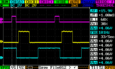
The ‘scope trace above shows… The Purple trace is the one it’s triggering one and that represents an output value of 10 – the vertical markers and the ΔT measurement shows 1mS which is right – 10 x 100μS pulses. If you count the dotted squares, there are 5 between the leading edges of the rising edge in the Purple trace which at 2mS per division is 10mS giving a PWM frequency of 100Hz.
The Yellow trace is an output value of 25 and the Cyan trace has an output value of 50.
Each PWM signal is generated by a separate thread so they all run independantly of each other. The traces are surprisingly steady though.
Finally, one of my infamous videos:
Gordon,
so you persuaded me to look at software pwm, I did a fresh pull of
https://github.com/WiringPi/WiringPi.
Maybe I missed something, but I can only see the examples for controlling the hardware PWM in ‘wiringpi/example/test2.c’.
Can you point me at the code that runs the above demo? or give me another hint? ta.
Do:
git clone git://git.drogon.net/wiringPi
then in wiringPi, you’ll find examples/softPwm.c and wiringPi/softPwm.c
-Gordon
Hi Gordon
I installed git and ran “git clone git://git.drogon.net/wiringPi” but it would not copy the new updates etc into my wiringPi directory saying “fatal: destination path ‘wiringPi’ already exists and is not an empty directory”
Is there a switch to force it to overwrite or should I delete the original wiringPi directory, in which case is there switch to delete directories that have contents with the “rmdir” command.
All the best
Paul
Hi Paul!
Must admit, I’m a bit of a GIT newbie myself, but slowly getting there.
I suspect the easiest thing to do is to rename the existing wiringPi (e.g.
mv wiringPi wiringPi.old
), then re-run the git clone command. you might want to keep it there for comparision, or if you’ve changed anything in the examples, etc., but if you want to remove the old one, thenrm -r wiringPi.old
Cheers,
-Gordon
To update existing git repo, git pull origin will do the job. 🙂 git pull will do a git fetch and git merge, so if you are modifying the library, it is better to just do a git fetch –verbose and merge the new update to your current branch manually.
Thanks for that – still learning GIT myself. I’ll update some of the pages I have with that once I’ve played with it myself!
Cheers,
-Gordon
awesome not least for running your own git server.
thanks
Excellent work Gordon! Would this be usable for controlling servo motors?
Rick
Possibly, but …
Radio Control type servos (which I assume you mean here) need a pulse width of between 1mS (hard left) and 2mS (hard right) followed by a long gap (which is used in the multiplexed PPM protocoll to send pulses to up to 7 other servos), so it’s somewhat different from regular PWM.
The pulse widths in this are intervals of 100uS, so to get 1mS you need a value of 10 and 2ms is a value of 20 – that only gives you 10 steps for the servo, so if it’s a typical 180 degree servo, each step is 18 degrees. This may be enough for your needs though…
Getting the pulse widths below 100uS is possible, but then the thread runs in a busy loop, polling a timer register, so realistically only one thread is possible.
-Gordon
Though you don’t actually need pulse widths below 100us for RC servos (the minimum pulse width is 1ms), simply steps of less than 100us to get finer control. Hence you don’t have an issue with going to a hard-loop when implementing this. I’ve had a look at the code – also the code for delayMicroseconds – and it certainly seems straightforward to modify by decreasing PULSE_TIME to decrease the step size, and simply limit the lowest value to a minimum value to keep minimum pulse width above 100us (you’d also want to choose a suitable initial value). I can’t see any reason why this wouldn’t work – though clearly accuracy is limited by the accuracy of nanosleep. Haven’t tried it yet, though, and reading through the comments below I see mention of an RC servo kernel module…
BTW PULSE_TIME isn’t actually used in the PI_THREAD function, you have ‘100’ hardcoded into the multiply for delayMicroseconds, so I’ve had to change that too!
I can indeed confirm it works fine with PULSE_TIME of 10, hence 10us resolution. I have rewritten softPwm.c to give this resolution, but still ensure minimum pulse width of 100us. Gives finer servo control than your original – though the servo position isn’t constant (as expected, since rpi doesn’t have a RTOS). However I can live with that for my application, and I can control the servo at the same time as playing analogue audio, which was the aim, and the reason for not using the hardware PWM (and also the reason why the kernel mode servo driver doesn’t work, as unfortunately that also uses hardware PWM for control). The whole point of porting my current project from an AVR to rpi was to make use of the built in audio!
The issue with the delat hardcoded to 100uS is because at under 100uS the wait is accomplished via a hard-coded loop poling a timer register. If you do it that way, then you can only have one task at a time delaying accurately for under 100us.
-Gordon
Yes, but the point is you don’t need to delay for less than 100us to control a servo, simply have resolution less than that for finer control – something which is prevented by setting the pulse time to 100us. Setting that to less than 100us doesn’t automatically result in the delay using the hardcoded loop – that only happens if the pulse time multiplied by the value is less than 100us, which you can prevent by other means. Here are my mods to softPwm.c to gives finer resolution without allowing delays less than 100us (I forgot to mention that the great thing about your code is that it’s easy to modify and recompile!):
#define PULSE_TIME 10
#define MIN_VALUE 10
.
.
.
if (mark != 0)
digitalWrite (pin, HIGH) ;
delayMicrosecondsShort (mark * PULSE_TIME) ;
if (space != 0)
digitalWrite (pin, LOW) ;
delayMicroseconds (space * PULSE_TIME) ;
.
.
.
void softPwmWrite (int pin, int value)
{
pin &= 63 ;
/**/ if (value (range [pin] – MIN_VALUE))
value = range [pin] ;
marks [pin] = value ;
}
Have a look at the new code I’ve emailled you – I don’t particulalry want to change the existing softPwm code, but would rather write new code pecifically to handle RC Servos.
However, for RC servos, there is a Linux kernel module avalable which should work far better than my userland approach – it might be worth while pursuing that way as it should be less prone to jitter than my code might be.
-Gordon
I’ve tried the kernel mode servo control which works very nicely, however as I mentioned before that is no good for my application as I need analogue audio. There are ways to reduce jitter with your code, but the only ones I’ve found so far do involve slightly higher processor loading due to needing to use a hardcoded loop – though you don’t need to use as long a hardcoded loop as you might think, so the processor impact isn’t that huge. There are also techniques to get multiple channels with precise timing, but at that point you’re definitely into the realms of something specific to servos rather than a generic PWM routine. Anyway to email…
Have sent you more email!
-Gordon
Hi,
I just install your librairy in my raspberry and write a small program to test PWM on three pins in the same time (for a RGB).
When I compile, gcc tell me: “pulseur.c:(.text+0xb4): undefined reference to `softPwmCreate'” but no probleme with “wiringPiSetupGpio()”
So I think that my library softPwm isn’t installed. There is something special to do? Or Have I to modify your Makefile?
Thank you!
Firstly, make sure you got the latest version and check it’s installed correctly.
Try this command to check:
nm /usr/local/lib/libwiringPi.a | fgrep soft
you should see something like:
softPwm.o:
000000e0 T softPwmCreate
00000000 t softPwmThread
000000b0 T softPwmWrite
If not, then let me know.
Then, make sure you are compiling with the -lwiringPi flags, so:
cc -o myProject myProject.c -lwiringPi -lpthead
Let me know if this helps (or not! It’s likely to be a simple installation issue and should be quick to resolve)
-Gordon
Hi, I am new in wiringPi
when a compile with -lpthead
cc -o myProject myProject.c -lwiringPi -lpthead
the follow error show
“/usr/bin/ld: cannot find -lpthead
collect2: ld retuned 1 exit status”
Can you help me?
What is wrong?
valeri
It should be -lpthread (missing ‘t’)
I’ll check my stuff in-case I’ve made a typo though.
-Gordon
Thank you for your reply!
I downloaded my version here: “https://github.com/WiringPi/WiringPi” today so it should be okay.
With your command:” nm /usr/local/lib/libwiringPi.a | fgrep soft” nothing happenned
But whithout the filter fgrep soft I have a list of your fonctions like pinmode.
Indeed it’s like my version is not the last one…
I’ve just done a fresh git clone and build on a Pi – (use the build script at the top-level to build and install it) and it seems fine for me.
Let me know if this doesn’t work for you and we’ll see if we can get to the bottom of it.
-Gordon
Well! The problem was solved by email!
So I have to use git to download the good version of wiringPi, if you use a direct download you have an older one without softPwm!
Thank you Gordon for your help,
Glad it’s going now.
Yes. The older download method is slightly behind the newer GIT based system. I do plan to keep both going for a while yet, though, just need to make sure that I update the older one a bit more often!
Cheers,
-Gordon
Great stuff! I have a bunch of IR codes stored on the Pi – trying to output these at 38KHz via an IR LED attached to the PWM pin. Not too worried about the real-time inaccuracies – just want to get something working.
Should I try a loop that turns the led on/off with some delayMicroseconds? Or try to adjust the Pi PWM defaults and use the PWM features similar to this Arduino code: https://github.com/shirriff/Arduino-IRremote ?
A pointer in the right direction would be really appreciated! I’ve been going round in circles trying this-and-that with no clear end in sight.
Cheers!
Dave
A 38KHz signal has a period of approximately 26uS, so you need 13uS on, 13uS off…
the softPwm I wrote here has a pulse width of 100uS, so isn’t suitable.
However, that’s achievable in a software loop using delayMicroseconds in current versions of wiringPi, however it’s a 100% cpu solution, but since you’re only transmitting pulses for a fraction of a second and probably not doing anything else, it’s probably going to be OK. Fine control may be an issue – e.g. drop to 12uS on and 12uS off and you’re now closer to 40KHz so it might well depend on just how fussy the reciever is in locking on to the 38KHz carrier.
The on-board PWM is capable of doing it – in theory.
Might be a nice little project to try though – will try to get some scope traces later today if I have time.
-Gordon
What about a kernel softpwm driver? That would solve most of the task scheduler issues
It would solve everything… However, while I’d love to do it, I don’t have the time right now to learn how to write a kernel module to do it – although there now is a kernel module for driving Radio-Control type servo motors which is really a variant of PWM, so maybe not that hard…
-Gordon
hello again! i’ve install from git and trying the gpio command. Have connected red led between gpio 18 and gnd, and a green led between gpio 18 and gnd. Then:
gpio -g mode 18 pwm
gpio -g pwm 18 800
and the red one bright, then try:
gpio -g pwm 18 100
and the red one, have very low bright, PERFECT!. Now i try:
gpio -g mode 17 pwm
gpio -g pwm 17 800
and the RED ONE bright again, why not the green one? whats i’m doing wrong?
The issue here is that the Pi only has one usable hardware PWM pin – GPIO 18. Pin GPIO-17 doesn’t have hardware PWM – that’s why it’s not working…
to use the softwarePWM – you need to write a program to run it – it can’t really be done at the command-line.
-Gordon
:'( i’m very noob in c but i think that we can do it’s a daemon in c with softwarePWM and a command-line command that call it and set a pwm or an output input value, don’t? The daemon is always running in background and we set values from a command (like now with gpio command), will be possible? any voluntary to develop it? 🙂 i repeat have no idea to program c, i only know bash.
It’s certianly possible to do something like that. If I have time next week, I’ll have a look.
-Gordon
Thanks for excellent work, Gordon!
Do you know how the gpio 18 hardware PWM frequency can be lowed?
gpio -g pwm 18 1
gives about 220ms interval between pulses (4.5kHz), but I’d like to be able to vary its smoothly from 1kHz to 5kHz.
TIA
PWM is an odd thing indeed.
And it’s odder on the Pi as it has 2 modes to operate in – traditional Mark:Space ratio mode or a balanced mode whereby the hardware tries to balance out the pulses to provide a more evenly spaced output. This is the default mode in the Pi.
Changing the frequency and the range (number of pulses) has proven to be somewhat problematic though, but I did recently put in some more code into wiringPi (with the help of someone else) to fiddle with the regsiters. Using gpio, try
gpio pwmc N
which will change the counter calue in the divider (default is 32)
gpio range N
which will change the range register (default is 1024)
gpio pwm-ms
will change it to mark:space ratio, and
gpio pwm-bal
will put it back to the balanced mode.
You may need a newer version of wiringPi though – use GIT to get the latest one.
-Gordon
Works great! Changing to mark:space makes the output very stable, no jitter (which appears in default mode).
Thanks!
Seems like all the videos on this site now all say “This video is private” 🙁
Hm. I’ve no idea what happened there – I’ve just gone through and changed them all to public. Most odd.
-Gordon
I can’t tell you how much I appreciate the wiringPi lib. Thanks! One thing-the GPIO header layouts for the Pi that I am able to find don’t seem to match up with the pin layouts (ie, pin 1 in test2.c corresponds to GPIO 18, header position 12.) Is there an infographic somewhere that maps the wiringPi pins to their GPIO header positions?
The Pins page has an image with all the details on it:
wiringPi Pins Page
-Gordon
Hi,
I am trying to include the softPwm functionality with my OpenNI code base since I want to control the motors based on the distance from the XBox Kinect. When I try including softPwm.h and call the function softPwmCreate in my main file, I get the following error.
pi@raspberrypi ~/NiSimpleRead $ sudo make
g++ -o ../Bin/Arm-Release/Sample-NiSimpleRead ./Arm-Release/NiSimpleRead.o ./Arm-Release/softPwm.o ./Arm-Release/wiringPi.o -L../../Lib -L../Bin/Arm-Release -lOpenNI
./Arm-Release/softPwm.o: In function `softPwmThread(void*)’:
softPwm.c:(.text+0x1c): undefined reference to `piHiPri’
./Arm-Release/softPwm.o: In function `softPwmCreate’:
softPwm.c:(.text+0x130): undefined reference to `piThreadCreate’
collect2: ld returned 1 exit status
make: *** [../Bin/Arm-Release/Sample-NiSimpleRead] Error 1
I understand its missing the -lpthread thing but I do not know how to edit the Makefile to include this.
Help me please !!!!
Are you cross compiling? If so, it’s an environment I’ve not tried myself, however..
The softPwm relies on the piHiPri () function and that’s defined in the wiringPi.h file, so make sure you #include <wiringPi.h> as well as #include <softPwm.h>
and you need to link with -lwiringPi as well as -lpthread
-Gordon
Thanks for the reply. It finally worked 🙂
Really appreciate the work and the library you’ve put together, Gordon. I find it immensely helpful.
Software-driven PWM is adequate for my servo. It’s simply responsible for rotating a webcam on my rover. This leaves pretty relaxed constraints on accuracy and performance.
The jittering when not rotating is a problem, however. To get around it I made an addition to softPwm.c:
void softPwmCreateAndSet(int pin, int value) {
pinMode (pin, OUTPUT);
digitalWrite (pin, LOW);
marks [pin] = value;
range [pin] = 100;
newPin = pin;
pthread_t myThread;
pthread_create(&myThread, NULL, softPwmThread, NULL);
while (newPin != -1)
delay(1);
delay(50);
pthread_cancel(myThread);
}
It essentially creates the thread, lets it run for a while to allow the servo to reach its position, then kills the thread. They key value here is the delay, which needs to be high enough for the servo to be able to keep up (depends on its speed) but low enough for decent response times.
This may or may not be the best approach but it seems to work for me. I can rotate my servo and it stands completely still when I’m not rotating it.
Looks intersting – as long as your servo doesn’t need continual “refreshing”…
-Gordon