
Did you know that the 8 inputs on the PiFace can be used as outputs too? Well they can, and this is something that I understand the boffins in Manchester who designed it had in-mind too… So in-between barbecues this (UK) bank holiday weekend, I’ve had some fun and adapted something I did on the Gertboard to the PiFace – Driving a 6-digit 7-segment display.
Here it is:
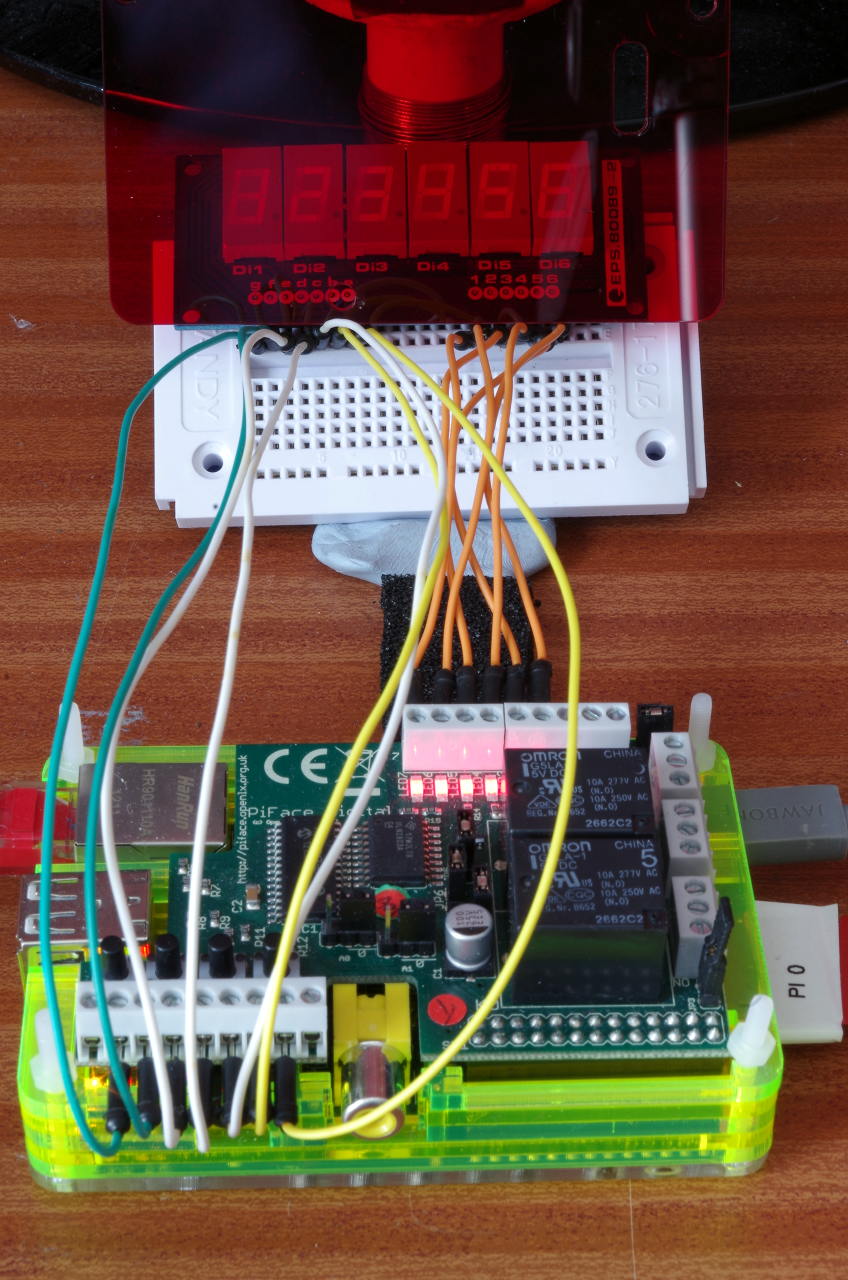 You can just make out the numbers 123456 on the LED digits at the top…
So how does it work: The Piface really is nothing more than an interface board with a standard SPI based GPIO expansion chip – the MCP23S17 which as 16 IO pins. 8 of these are connected to a ULN2803 open-collector buffer (darlington) chip – 8 of those 8 outputs go to on-board relays, the other 8 are uncommitted. On the input side – the 8 inputs pins go via 330Ω resistors to the terminals (and 4 buttons).
Pins 0-7 go to the ULN2803 and to the relays and output terminals and pins 8-15 go to the 330Ω resistors, the buttons and input terminals.
If we access the MCP23S17 directly, rather than use the wiringPi PiFace devLib for it, then we can re-provision the input pins as outputs and use them to drive things like LEDs.
(Well, not quite good enough for my display above – it’s over 25 years old, so old LEDs which have faded, and those old LEDs did need more current to drive them than the 330Ω resistors are allowing, but it’s the principle of the thing here!)
So how do we drive LED digits – easy here. We have 8 inputs which we’re using as outputs, so we can connect 7 to the 7 segments on the display and the common pin on each digit can go to one of the open collector drivers. To light up a single digit, we program the 7 segments as required, and enable the common line for that digit. Current flows out of the input pin, through the LED segments, and via the common pin for that segment into the open-collector driver on the PiFace and to ground.
To light up many digits, we repeat the above for each digit. ie
For each digit:
Set 7-segment pattern
Enable digit common-line
delay a short time
Disable digit common-line
This way, we can cycle through each of the 6 digits in-turn and if we do it fast enough then we don’t notice it happening (Look-up Persistence of vision)
We can illuminate all 7 segments at once, if required (e.g. to display an 8) as each one has it’s own limiting resistor and the “sink” pin goes via a darlington driver that can handle the combined current.
One thing to note here: This will only work with common-cathode type displays.
So there you have it – not quite “abuse” as it’s really by design, but something else to think about when using your PiFace board – if you need a 3.3v output and you have spate inputs, then re-provision one as an output and off you go.
Here’s the code for anyone interested:
/*
 * 7segments.c:
 *      PiFace "abuse". Use the inputs as outputs to drive a 7-segment
 *      LED display (common cathode) - connect the segments to the
 *      input pins, re-provisioned as outputs and use the darlington
 *      outputs as current sinks for each digit.
 *
 *      Copyright (c) 2013 Gordon Henderson
 ***********************************************************************
 */

#undef  PHOTO_HACK

#include <wiringPi.h>
#include <mcp23s17.h>

#include <stdio.h>
#include <time.h>
#include <ctype.h>
#include <string.h>

/*
 *  Segment mapping
 *
 *       --a--
 *      |     |
 *      f     b
 *      |     |
 *       --g--
 *      |     |
 *      e     c
 *      |     |
 *       --d--  p
 */

#define PF      200

// GPIO Pin Mapping

static int digits   [6] = {  PF+ 7, PF+ 6, PF+ 5, PF+ 4, PF+ 3, PF+ 2 } ;
static int segments [7] = {  PF+15, PF+14, PF+13, PF+12, PF+11, PF+10, PF+ 9 } ;

static const int segmentDigits [] =
{
// a  b  c  d  e  f  g     Segments

   1, 1, 1, 1, 1, 1, 0, // 0
   0, 1, 1, 0, 0, 0, 0, // 1
   1, 1, 0, 1, 1, 0, 1, // 2
   1, 1, 1, 1, 0, 0, 1, // 3
   0, 1, 1, 0, 0, 1, 1, // 4
   1, 0, 1, 1, 0, 1, 1, // 5
   1, 0, 1, 1, 1, 1, 1, // 6
   1, 1, 1, 0, 0, 0, 0, // 7
   1, 1, 1, 1, 1, 1, 1, // 8
   1, 1, 1, 1, 0, 1, 1, // 9
   1, 1, 1, 0, 1, 1, 1, // A
   0, 0, 1, 1, 1, 1, 1, // b
   1, 0, 0, 1, 1, 1, 0, // C
   0, 1, 1, 1, 1, 0, 1, // d
   1, 0, 0, 1, 1, 1, 1, // E
   1, 0, 0, 0, 1, 1, 1, // F
   0, 0, 0, 0, 0, 0, 0, // blank
} ;


// display:
//      A global variable which is written to by the main program and
//      read from by the thread that updates the display. Only the first
//      6 characters are used.

char display [8] ;


/*
 * displayDigits:
 *      This is our thread that's run concurrently with the main program.
 *      Essentially sit in a loop, parsing and displaying the data held in
 *      the "display" global.
 *********************************************************************************
 */

PI_THREAD (displayDigits)
{
  int digit, segment ;
  int index, d, segVal ;

  piHiPri (50) ;

  for (;;)
  {
    for (digit = 0 ; digit < 6 ; ++digit)
    {
      for (segment = 0 ; segment < 7 ; ++segment)
      {
        d = toupper (display [digit]) ;
        /**/ if ((d >= '0') && (d <= '9'))      // Digit
          index = d - '0' ;
        else if ((d >= 'A') && (d <= 'F'))      // Hex
          index = d - 'A' + 10 ;
        else
          index = 16 ;                          // Blank

        segVal = segmentDigits [index * 7 + segment] ;

        digitalWrite (segments [segment], segVal) ;
      }
      digitalWrite (digits [digit], 1) ;
      delay (20) ;
      digitalWrite (digits [digit], 0) ;
    }
  }
}


/*
 * setup:
 *      Initialise the hardware and start the thread
 *********************************************************************************
 */

void setup (void)
{
  int i, c ;

// 7 segments

  for (i = 0 ; i < 7 ; ++i)
    { digitalWrite (segments [i], 0) ; pinMode (segments [i], OUTPUT) ; }

// 6 digits

  for (i = 0 ; i < 6 ; ++i)
    { digitalWrite (digits [i], 0) ;   pinMode (digits [i],   OUTPUT) ; }

  strcpy (display, "      ") ;
  piThreadCreate (displayDigits) ;
  delay (10) ; // Just to make sure it's started

// Quick countdown LED test sort of thing

  c = 999999 ;
  for (i = 0 ; i < 10 ; ++i)
  {
    sprintf (display, "%06d", c) ;
    delay (400) ;
    c -= 111111 ;
  }

  strcpy (display, "      ") ;
  delay (400) ;

#ifdef PHOTO_HACK
  sprintf (display, "%s", "123456") ;
  for (;;)
    delay (1000) ;
#endif

}


/*
 * funTime:
 *      Jeremy Hillary Boob Ph.D. is a fictional character in the animated movie
 *      Yellow Submarine.
 *********************************************************************************
 */

void funTime (void)
{
  char *message = "      feedbeef      babe      cafe      b00b      " ;
  int i ;

  for (i = 0 ; i < strlen (message) - 4 ; ++i)
  {
    strncpy (display, &message [i], 6) ;
    delay (200) ;
  }
  delay (1000) ;
  for (i = 0 ; i < 3 ; ++i)
  {
    strcpy (display, "    ") ;
    delay (150) ;
    strcpy (display, " b00b ") ;
    delay (250) ;
  }
  delay (1000) ;
  strcpy (display, "      ") ;
  delay (1000) ;
}


/*
 *********************************************************************************
 * main:
 *      Let the fun begin
 *********************************************************************************
 */

int main (void)
{
  struct tm *t ;
  time_t     tim ;

  wiringPiSetup () ;
  mcp23s17Setup (200, 0, 0) ;

  setup   () ;
  funTime () ;

  tim = time (NULL) ;
  for (;;)
  {
    while (time (NULL) == tim)
      delay (5) ;

    tim = time (NULL) ;
    t   = localtime (&tim) ;

    sprintf (display, "%02d%02d%02d", t->tm_hour, t->tm_min, t->tm_sec) ;

    delay (500) ;
  }

  return 0 ;
}