
Where next?
I had a barely working 6502 prototype system on my workbench. It was a little unstable and didn’t like being moved, but it did work and demonstrated to me that the concept was viable.
Initially I didn’t know what I wanted other than “6502”… However some 30-40 years ago I did make some 6502 single board computers (SBC) and did a lot of programming on the Apple II and BBC Micro. I have also collected a few old Apple II’s and BBC Micros/Masters and one thing I had in my mind was to “re master”, or “re-imagine” what a 6502 computer system might be like with todays ideas and thoughts.
So the first task was to get a stable system and make it run BASIC.
Stripboard
Enter stripboard. Popular in the UK it’s been the staple of electronics hobbyists for decades. With a hand-held cutter (or in my lazy case an electric drill with suitable bit) good soldering skills and the ability to visualise your circuit you can achieve almost anything…
And so here it is:
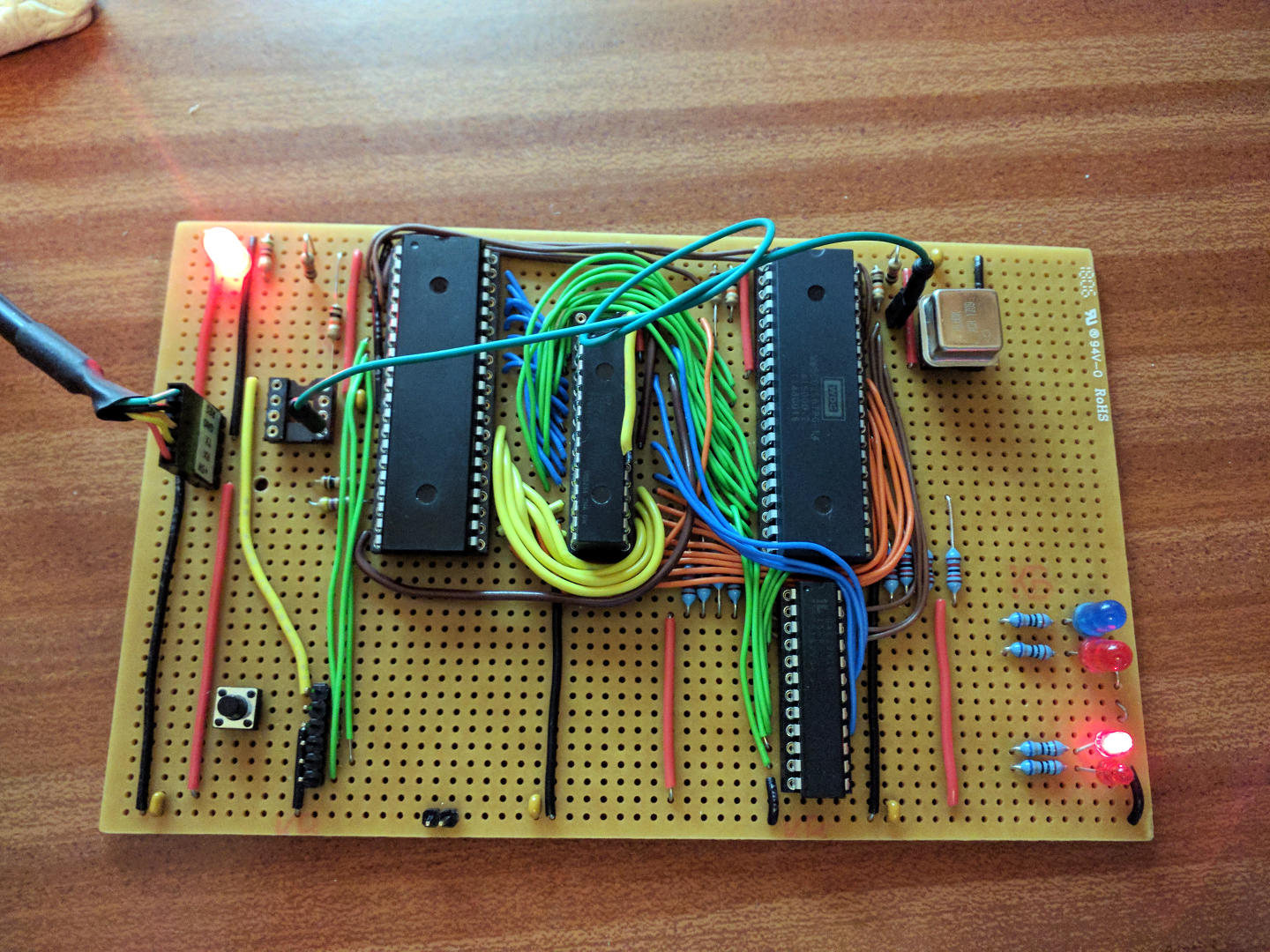
The chip layout differs slightly from the breadboard, from left to right: ATmega1284p, RAM (more on this shortly), 6502 and below that the GAL22v10.
There is no schematic for this – I knew what I wanted, printed out the data sheets for all the chips and set about wiring it up, one wire at a time.
Now that green wire that goes from next to the can oscillator on the right over to the left… It’s carrying a 16Mhz signal. These new WDC 65C02 chips can run at 14Mhz and so when I was buying bits I bought a few oscillators for it – the 16Mhz one was really for the ATmega, but on a whim I tried it in the 6502, after going 1, 2, 4 and 8Mhz. At 16Mhz, 2Mhz over the rated maximum and on stripboard it runs at 16Mhz and passes memory tests until the cows come home. That’s not too shabby, I reckon…
Memories….
And so the memory. Looks a bit odd there, perhaps? That yellow wire going over the top. Maybe this image will give a clue:
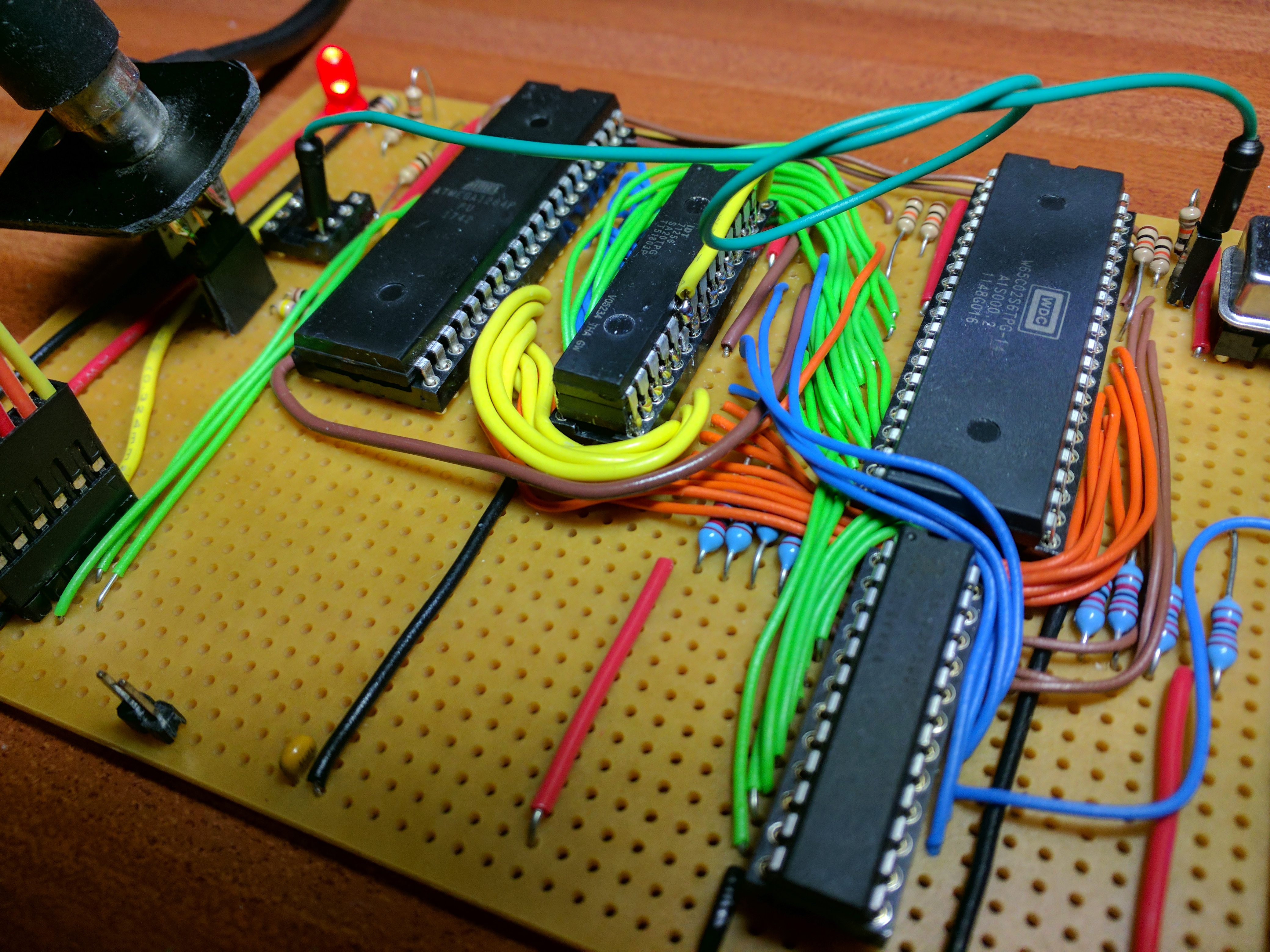
The RAM is 2 x 32KBx8 chips with one soldered on-top and it’s enable pin brought out separately. I’d not intended to do it that way, but why not – it works well and takes up less board space. I also know I’m not the first to do so either.
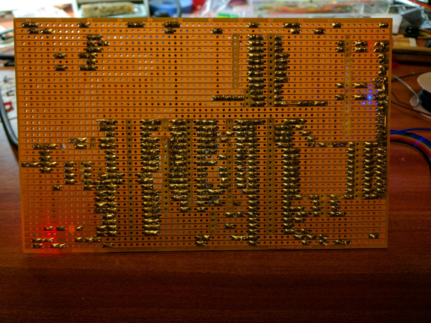
And for the curious, here is the back with all that lovely tin/lead solder:
But what can it do at this stage?
By this time I’ve added a little 8-bit latch and stuck my old LED board onto it. It’s running a binary count with each count representing a single pass of a simple memory test.
Next I’ll write about how it works, the memory map and exactly what the ATmega is doing.