Adafruit RGB LCD Plate with WiringPi

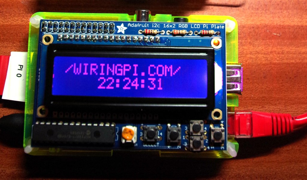
Part of my testing of wiringPi v2. was to make sure that some of the existing libraries code would work with GPIO expanders – and the Adafruit RGB LED Plate was an ideal candidate.

So I ordered one, took a few moments to solder it together and plugged it in – and 5 minutes later I had my LCD test program working without any real issues.

adaLcd

So if you want to drive one of these from C/C++ or anything else that uses wiringPi, then be assured that it’ll just work!

Comments

Adafruit RGB LCD Plate with WiringPi — 4 Comments

  1. Hi Gordon,

    i’am trying all your nice examples and never bevor had any Problems.

    But now with lcd-adafruit i have no success.
    GPIO version is 2.07, the Adafruit RGB LCD Plate is working perfect with all of the Adafruit examples.
    If your example programm is opened with “sudo ./lcd-adafruit colour”
    it switches the background colour to green, doesnt clear the Display
    (if there is anything in) and tells me to press the select key.
    But there are no further reactions at the LCD.
    What am i missing?
    Regards Olaf

    • Not sure what’s missing. Ive just plugged my display into a pi and

      gordon @ pi0: ./lcd-adafruit 2
      Raspberry Pi Adafruit LCD test
      ==============================
      Unable to open I2C device: No such file or directory
      gordon @ pi0: gpio load i2c
      gordon @ pi0: ./lcd-adafruit 2
      Raspberry Pi Adafruit LCD test
      ==============================
      Press SELECT to continue: OK
      Press SELECT to continue: OK
      Press SELECT to continue: OK
      Press SELECT to continue: OK
      Press SELECT to continue: OK
      Press SELECT to continue: OK

      Worked straight away.

      (No need to sudo if you use the gpio command to load i2c)

      If it did the display colour OK, then it indicates that it’s talking to the mcp23017 on the board OK. Try different colours to make sure – 0 is off, 7 white.

      -Gordon

      • Hallo Gordon,
        what a wonderful program. Now it’s doing what you intended.
        My faults where two wrong entries:
        : gpio load i2c –> was missing
        and
        : ./lcd-adafruit red (or green or blue…) is wrong.
        Didnt know about the numbers 0 to 7.
        Thank you so much for your answer.
        Olaf

        • Glad its going now!
          Yes, I was a bit lazy over the colours – work it out as an excercise, but bit 0 is red, bit 1 is green, bit 2 is blue, so to make it blue, use 4 …

          -Gordon