
The Quick2Wire project has been in the process of designing some new interface boards for the Raspberry Pi for some time and now they have some hardware!
I got a kit from them recently comprising the main board and the GPIO expander board – soldered it up without too much difficulty and here it is:
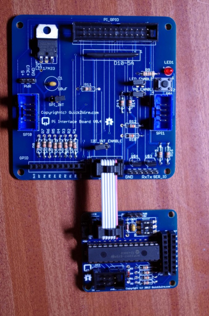
Quick2Wire board and GPIO expander
The main board connects to the Raspberry Pi with a standard 26-way ribbon cable. To the left and right of the main board are expansion sockets for SPI devices and at the bottom is an 8-way GPIO connector and the I2C connector. I2C boards can be connected in series, so the board I have here has a 2nd I2C connector for the next board along.
On the main board, there is an 8-way connector for the Pi’s own GPIO connections. This is protected by resistors and zenier diodes in the same way as Mike Cooks Pi Breakout Board. This means that you can connect it directly to LEDs without any series protection resistors and that it’s also tolerant of 5v (or maybe more) going into the board accidentally.
The main board has a 3.3v voltage regulator which is passed to the peripheral boards. This takes the load off the Pi’s own 3.3v supply.
It also features an LED and a button – these are connected to pins 1 and 0 respectively, but via little jumpers, so if you need to use those pins for other uses, then you can.
Finally, on the main board there is a buffered serial port connected to the Pi’s on-board UART. This will drive standard 5v TTL type devices and be safe when driven by them too.
Using the board is very easy – the 8 GPIO pins are numbered 0 to 7 and use the same pin numbering scheme as wiringPi (And as I understand it, Quick2Wires own Python libraries use this numbering scheme too)
I used the gpio command in wiringPi to give it a test and didn’t have any issues.
So:
gpio mode 0 in
gpio mode 1 pwm
gpio read 0 # Read the button
gpio pwm 1 500 # On-board LED to half brightness.

# Simple LED blink
gpio mode 1 out # Normal output
while true; do gpio write 1 1 ; sleep 0.5 ; gpio write 1 0 ; sleep 0.5; done
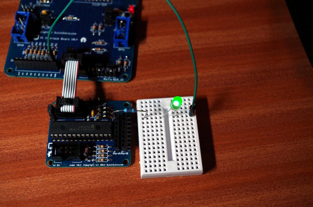
Taking advantage of the on-board resistors, I connected an LED directly between pin 2 on the mainboard and 0v, and
gpio mode 2 out
gpio write 2 1
and it lit up, as expected.
The I2C expansion board was easy too – I used gpio to load the I2C modules into the kernel (which then allows the user to access them without sudo, then the standard i2cdetect to probe the bus:
gpio load i2c
i2cdetect -y 1 # Rev. 2 Raspberry Pi, I2C device 1

     0  1  2  3  4  5  6  7  8  9  a  b  c  d  e  f
00:          -- -- -- -- -- -- -- -- -- -- -- -- --
10: -- -- -- -- -- -- -- -- -- -- -- -- -- -- -- --
20: 20 -- -- -- -- -- -- -- -- -- -- -- -- -- -- --
30: -- -- -- -- -- -- -- -- -- -- -- -- -- -- -- --
40: -- -- -- -- -- -- -- -- -- -- -- -- -- -- -- --
50: -- -- -- -- -- -- -- -- -- -- -- -- -- -- -- --
60: -- -- -- -- -- -- -- -- -- -- -- -- -- -- -- --
70: -- -- -- -- -- -- -- --
Device 0x20 is the I2C code for the MCP23017 GPIO expander chip, so it was detected correctly. The expansion board has a set of switches which allow for it to be set to 8 different addresses, (0x20 through 0x27) so it’s possible to have up to 8 of these boards connected if required!
A quick little program later in C, using my new wiringPi I2C helper functions and it’s working just fine:
Quick2Wire I2C Expander in use
I’ve temporarily put the program here: http://unicorn.drogon.net/q2w.c but will likely be moving it and writing something to integrate the Q2W boards better into wiringPi.
So, a nice little main board with easy to add expansion boards using SPI, I2C and the Pi’s on-board GPIO.