From the Wikipedia entry:
The Little Man Computer (LMC) is an instructional model of a computer, created by Dr. Stuart Madnick in 1965. The LMC is generally used to teach students, because it models a simple von Neumann architecture computer – which has all of the basic features of a modern computer. It can be programmed in machine code (albeit in decimal rather than binary) or assembly code.
This implementation is written using RTB on the Raspberry Pi and allows manual data entry via the computer control panel or you can use the built-in assembler to load files in its assembly language.
I have added some extensions to LMC to modernise it from its 1965 roots. The first is the JSR and RET instructions. JSR is Jump to Subroutine and RET is return. In keeping with the simplicity of the system, there is only one register to store the program counter for the RET address. The other additions are for the Raspberry Pi’s GPIO. You can read a pin or set a pin to high or low. See the examples for details.
The RTB/Raspberry Pi implementation features three running modes – one is slow and runs at 10 instructions per second. This allows you to visually see the memory and accumulator changing as well as the program flow, the second is fast mode – the output register is updated, but that’s all, and finally you can single-step a program.
Download and Install
First you need RTB installing on your Raspberry Pi. See here for full details.
Obtaining the LMC software and examples:
cd
git clone git://git.drogon.net/lmc
that will create a directory called lmc and download the code and examples into it. Once that’s complere you can start rtb and load the code and off you go:
cd lmc
rtb
(then inside RTB)
load lmc
run
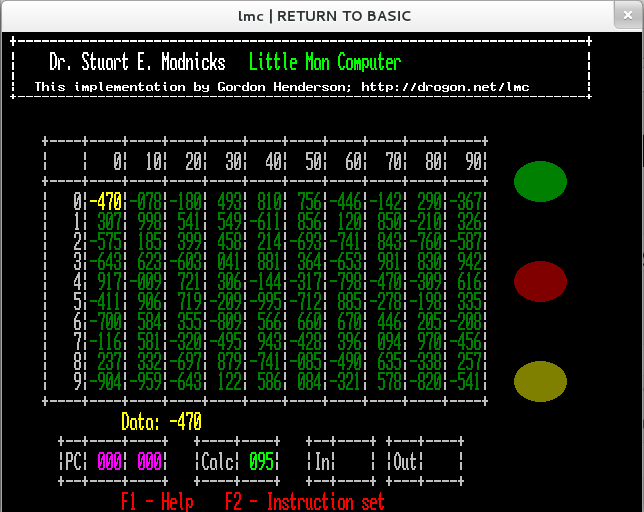
And you should see the main computer screen:
 The main memory array is in the middle (full of random numbers at start time), the indicators on the right are Run (Green), Error (Red) and Input (Yellow). All are shown in their “off” state here.
The Yellow number and text in the middle is the current instruction or data that the program counter is pointing to and the bottom four boxes contain the program counter and saved program counter values, the calculator (accumulator) and the input and output registers.
When the program is running in slow-mode, the current instruction is highlighted in Pink with the disassembly also in Pink.
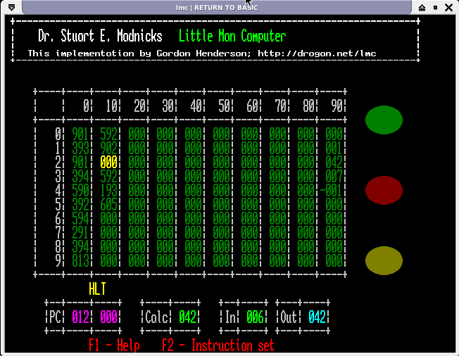
 This is the LMC screen at the end of a run of the multiply.lmc program when asked to multiply 6 by 7.
Operation
The LMC is controlled by simple key-presses. On the main screen, you can move the active location (memory address highlighted in Yellow) using the arrow keys. To manually enter data or an instruction just type the numbers – the memory locations will only take the last 3 digits typed. Entering 1234 will result in 234 being placed into the memory location. Use the minus key (-) to negate the value. Pressing the Enter key moves to the next memory location.
Note some commands are case-sensitive.
- Z (Capital Z) Zeros the computer.
- R (Capital R) Runs the program from location 0 at full speed. Only the output register is updated in this mode.
- r (Lower case r) Runs the program from location 0 in slow mode. This is a rate of 10 instructions per second with the display being dynamically updated as the program runs.
- S (Upper or lower case) Single-Steps the program from the current program counter. (ie. if you need to start it at location zero, then you need to move the highlighted location to zero first)
- L (Upper or lower case) loads in a new assembly program (ie. with mnemonics, not binary code!)
- A (Upper or lower case) Assembles the previously loaded program into the numerical form and stores it in the LMC memory.
The reason there are separate Load and Assemble commands is because a running program may alter its data, so a 2nd run of the same program may start off with the wrong values unless you write additional code to correctly initialise a location, or separate locations containing constants and variables. With the separate commands here, you can load a program once, assemble and run it many times.
So typically, you would load a program once (L command), Zero the memory (Z), Assemble the program which loads it into memory (A) then run it.
Programs may be edited using any text editor you are familiar with. I’d suggest using nano if you are new to text editing on the Raspberry Pi.
During a program run, pressing the space-bar will stop the program. This works at all times, even when waiting for input.
When the program executes an INP instruction, execution is paused and you can enter a number into the Input register location in the same way as entering a number in the main memory array. Terminate number entry with the Enter key. Pressing the space-bar at this point will abort the program run.
Architecture
The LMC has 100 memory locations (called mailboxes in the original documentation), one program counter, one calculator (or accumulator in modern terms) and (as an extension here), one saved program counter for the JSR/RET instructions. The calculator/accumulator and the memory locations can hold a number from -999 to 999 and the program counter (and save program counter) can hold memory addresses from 0 to 99.
Additionally there is an input register and an output register. Programs can stop and read from the input register (keyboard entry) or post a value to the output register at any time.
There are many online references for LMC, but I will put the table of op-codes here for reference (And you can see them in the program itself with the F2 key)
| Opcode | Mnemonic | Instruction | Description |
| 000 | HLT | Halt | Stops program execution. It’s time for the little man to take a coffee break! |
| 1xx | ADD | Subtract | Adds the value of the memory location xx to the calculator and stores the result back in the calculator. |
| 2xx | SUB | Subtract | Subtracts the value of the memory location xx from the calculator and stores the result back in the calculator. |
| 3xx | STA | Store | Stores the value in the calculator into memory location xx. |
| 4xx | JSR | Jump to Subroutine (Extension) | The program counter is incremented, stored in the saves program counter register and a jump is performed to the memory location xx. |
| 5xx | LDA | Load | Loads the value held in memory location xx into the calculator (accumulator) |
| 6xx | BRA | Branch | Copies the address xx into the program counter. ie. the next instruction executed will be the one in memory location xx. |
| 7xx | BRZ | Branch if Zero | Tests the calculator (accumulator) and if it is zero, then the branch to memory location xx is taken. |
| 8xx | BRP | Branch if Positive | Tests the calculator (accumulator) and if it is positive (>= 0) then the branch to memory location xx is taken. |
| 901 | INP | Input | Reads the value from the input register into the calculator. Program execution is halted while the user types the value into the computer. |
| 902 | OUT | Output | Copies the value in the calculator (accumulator) to the output register. |
| 903 | RET | Return (Extension) | Returns from a subroutine after the JSR instruction. This copies the value in the saves program counter into the program counter. |
| 910 | GIN | GPIO Input (Extension) | Reads the value of the GPIO pin addressed by the calculator into the calculator. The result will be 1 or 0. |
| 911 | GHI | GPIO Output Hi (Extension) | Writes a 1/High value on the GPIO pin addressed by the contents of the calculator. |
| 912 | GLO | GPIO Output Lo (Extension) | Writes a 0/Low value on the GPIO pin addressed by the contents of the calculator. |
In addition to the above, there are 2 extra mnemonics used by the assembler. The first is DAT which is used to pre-load a memory location with a data value and the second is ORG. This is an extension which changes the location of the store pointer at program assembly time. Normally it starts at zero and is incremented for every instruction, but using this, you can place instructions and data at any location. This may be used to help view the data section in the run-time display of the computer which is arranged in 10 columns of 10 memory locations.
GPIO Access
The pin numbers used are the wiringPi pin numbers by default. If you want to use the native BCM pin numbers then you need to start RTB with the -g flag. To use the P1 numbers then start wiringPi with the -1 flag. (These are the same flags used to control the gpio program) Note that the BCM pin numbers are different between Rev 1 and 2 boards.
To simplify the GPIO access, there is no pin direction control – the GIN, GHI and GLO commands will set the directions as required.
Examples
There are a few examples provided:
- countd.lmc
- square.lmc
These are the examples in the LMC Wikipedia page. I have changed the square.lmc program to use the ORG pseudo instruction to place the constants and variables starting at location 90. That separates them from the program code so you can more easily see them changing as the program runs.
- multiply.lmc
- divide.lmc
Example to multiply and divide 2 numbers together. The program stops and you enter the first, then the second number and it calculates the result. (first * second, or first / second)
- blink.lmc
- blink8.lmc
Blink is the ubiquitous blink example which flashes the LED on pin 0 (BCM_GPIO 17). Blink8 does a simple sequence of the first 8 pins/LEDs. (wiringPi numbers 0-7) I tested it on my ladder board. If you have a Pibrella board, then blink will toggle the Yellow LED. blink8 will run on it, but would need changing (left as an exercise to the user 🙂
- pibrella.lmc
If you have a Pibrella board from Pimoroni plugged into your Pi, then this is a very simple traffic light program. Run it is slow mode. When started, it will light the Green LED and wait for the button to be pushed. When pushed, it will cycle green -> Yellow -> Red, then wait for 5 seconds or so, then cycle back again. It’s also a demonstration of the JSR/RET op-codes too.
