I’ve been asked to include SPI (and I2C – more on that soon) support for the Raspberry Pi in my wiringPi… However because it’s hard to anticipate exactly what SPI devices you may connect up, it’s hard to provide something specific, so what I’ve done is provide some “helper” functions in a library and a guide on how to use SPI and what it’s all about…
SPI – Serial Peripheral Interface
SPI is an interface developed (or named?) by Motorola which is a Synchronous serial clocked, full-duplex master/slave bus….
That’s a mouthful. In essence, data is sent out synchronised (or locked) to a clock signal which is also sent out (so 2 wires), there is a separate wire for incoming data (3 wires, so data can be sent and received at the same time, so full-duplex) and a fourth wire to act as a “chip select” signal. Because of this, it’s sometimes called a 4-wire bus. The master/slave part indicates that any device on the bus can start a transmission to any other device on the bus. There can be multiple chip-select wires to talk to multiple devices on the same SPI bus.
The Raspberry Pi only implements master mode at this time and has 2 chip-select pins, so can control 2 SPI devices. (Although some devices have their own sub-addressing scheme so you can put more of them on the same bus)
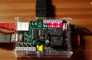
One thing to remember about SPI is that to receive a byte, you need to send a byte. This may sound a little odd, but consider a device which accepts a command byte, then a data byte, then sends back a result byte… To make this happen, we need to send three bytes to the device, which will send back 2 dummy bytes, followed by the 3rd byte with data in it. For example, a GPIO expander chip (e.g. the MCP23S17 as used in the PiFace) where you send it a command (read register), then the data (the register number), then it sends back a return value (the register contents). So, when you send the command, it will send back a byte which you ignore, you send it the data, it sends back a byte which you also ignore, but to make it send the result, you need to send it a third byte which it will ignore!
Another example is the MCP3002 2-channel, 10-bit analog to digital converter chip as used the the Gertboard – that chip actually uses the SPI clock signal to drive its internal logic. The command sequence you send to it is only 4 bits long, but you get 10 bits of data back from it, starting one bit after the last command-bit… so you need to send it 2 bytes and read 2 bytes back from it, and in the 2 bytes back, the data starts at the 5th bit and extends for 10 bits, so to keep the clock going, you need to send 2 bytes, read 2 bytes then pick the 10 data bits out of the returning 16 bits…
So it’s not always obvious!
Installing the kernel driver
The Linux kernel in recent Raspberry Pi releases supports the SPI as a native device (no more bit-banging!) but it’s disabled by default, so we need to load the module before we can use the SPI device. Additionally we may need to change the permissions and/or ownerships of the files in /dev/ so that we can access them from out programs without needing to be root or run them with sudo.
The easiest way to do this is with the gpio program that’s part of wiringPi:
(Instructions to get and install wiringPi are here)
gpio load spi
That command will load the SPI driver and change ownership to the user running the command. Once we’ve done that, we can then run our SPI programs.
If you want to do it the hard/traditional way, then:
sudo modprobe spi_bcm2708
sudo chown `id -u`.`id -g` /dev/spidev0.*
Use the lsmod command to make sure the modules are loaded.
Using SPI
WiringPi provides a small library to help hide most of the issues dealing with opening and sending bytes to/from SPI devices, however if you need something that’s outside what this library can do, then you’ll need to write your own – however the library code is easy to follow, so you should be able to use that as a basis for your own code.
These are documented elsewhere, but in-essence:
if (wiringPiSPISetup (channel, 1000000) < 0)
  fprintf (stderr, "SPI Setup failed: %s\n", strerror (errno))
will get you going (channel is 0 or 1, the 1000000 is the speed – 1MHz here) and:
wiringPiSPIDataRW (buffer, size) ;
will then perform a concurrent transmit and receive of the contents of the buffer (unsigned chars) of the given size. Note that the buffer will be overwritten.
Do have a look at the gertboard.c library for examples of this code – in particular the analog read function, where it sends a command to the SPI A/D converter and reads back the data in the same transaction – then picks the data out of the return bytes.
Abusing SPI
Abusing is perhaps a harsh word here, but it’s possible to use the SPI bus for things that weren’t designed for SPI – one example is shift registers. Just use the clock and MOSI outputs, and write a byte at a time to the SPI device. Another use is the daisy-chained LED strings that are now available at a reasonable price – you can send up to 4096 bytes at a time which might represent a string of over 1000 LEDs, each accepting a 3-byte value, then pause (typically 500μS) to make the devices display the pattern.
SPI Speed?
An important aspect of SPI is that the clock can (usually) be driven at varying speeds – the dependence is usually on the peripheral device being driven. E.g. the analog to digital converter on the Gertboard must be driven at a speed between 1MHz and 3MHz – however the upper limit is the voltage it’s supplied with (3MHz max. at 5v), so it’s important to know in-advance what limitations of the devices you are talking to.
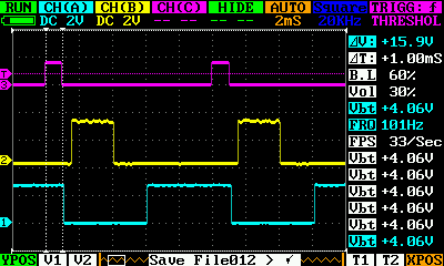
To experiment with timings, I wrote a little test program to see the effects of the different speeds – starting at 0.5Mb/sec going up to 62Mb/sec. I simply looped the MOSI and MISO pins together and checked that the data received was the same as the data sent.
The first thing I found was that the Pi stops sending at clock speeds over 62Mb/sec., and that in-reality 32Mbs is the upper limit of the SPI clock.
Next, I noticed that for some clock speeds, the data rate doesn’t change – this is due to the rounding issues when calculating the clock divider value. What I have observed is that the speeds available are:
- 0.5 MHz
- 1 MHz
- 2 MHz
- 4 MHz
- 8 MHz
- 16 MHz and
- 32 MHz.
You can see the progression, it’s powers of 2, and this reflects the clock divider values too.
The important thing to realise is that if you are clocking a part designed for a SPI clock rate of 25MHz, then setting the clock to 25MHz will really create a clock of 16MHz. There is no way to get an exact 25MHz clock speed. This probably isn’t important, and the reality of trying to send a 25MHz signal down a pair of wires or along a PCB track is that it’s highly likely to not work unless you take good care with the signal routing, shielding and so on.
Another observation was that the overheads in the Linux kernel increase with clock speed and the data throughput doesn’t quite increase linearly with clock speed. So with a clock at 1MHz we get a throughput of 0.108 MB/sec, at 2MHz it’s 0.214 MB/sec and it more or less doubles up to 16MHz (1.55MB/sec) but at 32Mb/sec clock, it’s barely 2.2MB/sec when you might expect it to be closer to 3MB/sec.
Finally, it’s worth while noting that the actual latency of calling the wiringPiSPIDataRW() function is rather high – an example I tested was sending 2 bytes at a time to the Gertboards digital to analog converter and rather than the 50,000 updates/sec I was expecting I was seeing barely half that, and a few experiments shows that it wasn’t that tied to the SPI clock frequency either.
Summary:
SPI is easy to use and can be fast. Be aware that communication is full duplex and data comes back at the same time as you send it, so be prepared to pick bits out of the return data – often at funny bit offsets, rather than byte offsets. The Pi can only directly drive 2 SPI channels, but some devices have their own sub-addressing scheme to allow for more on the same bus.

