Ruby 6502 – More hardware details

How does it work?

The 6502 (or W65C02S in our case) is really designed to have some ROM (or modern flash, etc.) to enable it to boot. At power on or reset, it reads an address out of a fixed location normally stored in ROM and jumps to it. That code then does what’s needed to make the system get going.

And here we have a small issue: The Ruby has no ROM…. So why not, and how to make it work?

No ROM

One reason was to simplify the hardware. ROMs are typically, relatively slow, even by the very old 6502 standard. To make matters worse, the 6502 has a somewhat interesting way of accessing memory that means the memory has to be at least capable of responding in half the time you might expect. So for a 1Mhz 6502, you might expect a 1-microsecond access time, however it really needs just under 500nS. Take that to the maximum speed that a modern W65C02S is rated for which is 14Mhz and you need better than 70nS. In reality, you actually need better due to the latency/propagation delay of signals going from the 6502 through e.g. address decoder before it gets to the ROM chips. The same timings apply for RAMs too.

Also the 6502 only reads or writes the memory for half a clock cycle and this was taken advantage of by the various video generation circuitry of the early microcomputers such as the Apple II – 6502 runs flat-out, but does it’s RAM access in half a cycle, the video jumps in on the other half cycle and pulls data out to send to the display.

So we need (relatively) fast ROMs, and there weren’t any suitable. I was aiming for classic through hole technology too. There’s also the issue of having to reprogram them. I did this regularly over 30 years ago and it quickly becomes a chore, so I decided to go for an all RAM solution.

RAM chips are still available in through-hole technology, fast enough and with the capacity I needed, although I ended up with 2 32K x 8 bit chips as there were no suitable 64Kx8 ones.

The issue now – how to get data into the 6502 in the first place.

Enter the ATmega.

I had been experimenting with using an ATmega to generate composite video and had a system using an ATmega1284p which has 16KB of internal RAM and was generating a nice 320×240 pixel monochrome display, so I went about working out how to interface that to the memory system with the aim of using that as it’s video output. (I’ve since put that idea on hold – more on that later)

And this is where a modern version of the 6502 works well. The WDC 6502s which are still being made today have a couple of features that work well here. One is the BE or Bus Enable signal. Pull this low and the 6502 immediately tri-states all its address and data lines. The other is the Rdy signal. Pull this low and the 6502 stops at the end of the current clock cycle. So, it’s a simple matter of halting the 6502, disabling its bus, connecting the bus to the ATmega and having the ATmega fill the RAM, then reverse the process and let the 6502 boot. What could possibly go wrong …

Almost.

The 6502 has a single Read/Write output pin. the RAM needs separate Read and Write inputs. There are also 2 RAM chips and I want to decode a block for some IO devices…

Enter the GAL…

A GAL is the pre-cursor to the FPGA. It’s a Generic Array of Logic. Initially one-time programmable (PALs), the GAL can be re-programmed 100 or so times. They were popular in the early 1980’s to the mid 90’s when the ULA was being used in home computers such as the BBC Micro and ZX Spectrum. In the Ruby it’s doing the job of sorting out the read and write signals, working out which enable signal to send to the RAM chips and enable some IO decoding to be performed. As a bonus I can hook up an LED or 2 to help with debugging if required.

There is a minor issue with GALs these days – Lattice stopped making them a few years ago an dsupplies from the mainstream outlets have all dried up. Atmel (now Microchip) are still making new GALs, however I lack the programmer to correctly program them and programmers that can program the Lattice ones simply won’t work, so right now I’m sourcing them from what appears to be reliable component recycles in China and so-far they’re all working perfectly.

The memory map

The 6502 divides it’s 64KB of memory up into 256 byte pages and it needs RAM in page 0 ($0000 -> $00FF) and page 1 ($0100 -> $01FF). This is for fast data storage and the stack. The reset vector (and interrupt vectors) are at the top of memory ($FFFA -> $FFFF) which is normally ROM, so I arranged the system so that the top page from $FF00 through $FFFF was the page that was shared with the ATmega. This needs 8 pins from the ATmega for the data bus and 8 for the address. Also a few more to control the 6502 Reset input, Rdy and BE signals, as well as read and write. The resulting memory map looks like:

$0000 -> $FDFF: RAM
$FE00 -> $FEFF: 256 bytes of IO space
$FF00 -> $FFFF: 256 bytes of RAM shared between the 6502 and ATmega

It’s quite simple and easy to decode inside the GAL and leaves the maximum amount of RAM for program and data usage.

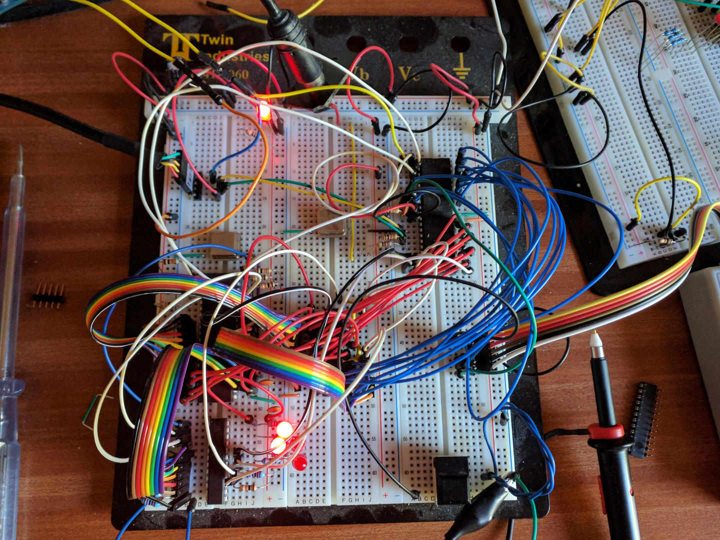
On the breadboard version there was no real IO – just a pin I could connect to a ‘scope. On the stripboard version there was an 8-bit latch I could use and on the PCB version there is a WDC65C22S VIA with it’s dual parallel ports, timers and other features.

So at power on, the ATmega controls the system. It holds the 6502 in reset and pulls the BE pin low to cause the 6502 to tri-state it’s buses. It copies the minimal bootloader into the shared memory page which includes the reset vector then releases the memory (tri-states the pins used for address and data lines), lets the 6502 access the memory and takes it out of reset.

The 6502 wakes up, reads the reset vector and jumps to it. (This is $FF00 initially) That code relocates itself to a lower location in RAM then communicates with the ATmega to get more code to finish the bootstrap process.

The communication is fairly straightforward and relies on another trick of the W65C02S – the Rdy pin is bi-directional and there is a new instruction; WAI which causes the 6502 to halt, pull Rdy low then wait for an interrupt. The ATmega meanwhile has been reading the Rdy pin and when it sees it going low, it switches the bus RAM control over, reads a command and data out of the shared memory page and does whatever it’s commanded to do. For example, it might be asked to load block 5 of the bootloader, so it copies that block from it’s own internal flash to the shared memory then switches the bus control back to the 6502 and sends an interrupt to the 6502 which causes it to wake from the WAI sleep and carry on.

And that’s the key to the 6502s communications. Everything happens via the small page of shared RAM – a virtual serial port, simple ROM filing system and a full-featured filing system that can use the spare RAM on the ATmega or it’s NVRAM or an external SD card as file storage.

It’s not a million miles away from the BBC Micro, however in this case, once the 6502 has booted, it’s really the master of the system. The ATmega is a multi-function peripheral device that just helped to boot the 6502 in the first instance.

From now on, it’s 6502 code time and I’ll talk about that next.

Back to the Ruby 6502 index page

Ruby 6502 on Stripboard

Where next?

I had a barely working 6502 prototype system on my workbench. It was a little unstable and didn’t like being moved, but it did work and demonstrated to me that the concept was viable.

Initially I didn’t know what I wanted other than “6502”… However some 30-40 years ago I did make some 6502 single board computers (SBC) and did a lot of programming on the Apple II and BBC Micro. I have also collected a few old Apple II’s and BBC Micros/Masters and one thing I had in my mind was to “re master”, or “re-imagine” what a 6502 computer system might be like with todays ideas and thoughts.

So the first task was to get a stable system and make it run BASIC.

Stripboard

Enter stripboard. Popular in the UK it’s been the staple of electronics hobbyists for decades. With a hand-held cutter (or in my lazy case an electric drill with suitable bit) good soldering skills and the ability to visualise your circuit you can achieve almost anything…

And so here it is:

Ruby 6502 on stripboard

The chip layout differs slightly from the breadboard, from left to right: ATmega1284p, RAM (more on this shortly), 6502 and below that the GAL22v10.

There is no schematic for this – I knew what I wanted, printed out the data sheets for all the chips and set about wiring it up, one wire at a time.

Now that green wire that goes from next to the can oscillator on the right over to the left… It’s carrying a 16Mhz signal. These new WDC 65C02 chips can run at 14Mhz and so when I was buying bits I bought a few oscillators for it – the 16Mhz one was really for the ATmega, but on a whim I tried it in the 6502, after going 1, 2, 4 and 8Mhz. At 16Mhz, 2Mhz over the rated maximum and on stripboard it runs at 16Mhz and passes memory tests until the cows come home. That’s not too shabby, I reckon…

Memories….

And so the memory. Looks a bit odd there, perhaps? That yellow wire going over the top. Maybe this image will give a clue:

Another view of the stripboard 6502

The RAM is 2 x 32KBx8 chips with one soldered on-top and it’s enable pin brought out separately. I’d not intended to do it that way, but why not – it works well and takes up less board space. I also know I’m not the first to do so either.

And for the curious, here is the back with all that lovely tin/lead solder:

The reverse of the Ruby 6502 stripboard

But what can it do at this stage?

By this time I’ve added a little 8-bit latch and stuck my old LED board onto it. It’s running a binary count with each count representing a single pass of a simple memory test.

Next I’ll write about how it works, the memory map and exactly what the ATmega is doing.

Back to the ruby 6502 index page

My 6502 system

A 6502 SBC: Working prototype

To mark my own use and knowledge of 40 years of the 6502, I decided to build my own little single board computer (SBC) based on it.

I had a few ideas in-mind – one was to make it a little faster than the old ones (but I really didn’t mind), one was to make it suitably “retro” and try to use the sorts of components available round about my target date – so this meant through hole components rather than surface mount. I also wanted to try to keep the hardware fairly simple.

My initial aim was for a stand-alone system with video output and keyboard input. Also a serial port for software download, blinkenlights, of-course and as much RAM as possible.

And then I hit a snag. Several, actually. The first one was that the old video controller chips are no-longer being made. Plenty on ebay, but…  Next was the keyboard interface – but PS/2 type keyboards are easy to come-by and relatively easy to use. Memory, and ROM/EEPROM… The 6502 has a unique (that I’m aware of!) way of accessing memory – it only accesses it on half a clock cycle rather than use a full clock cycle. The effect of this is that you actually need memory that’s twice as fast as you might first imagine. So for a 1Mhz 6502, you might think that memory with a 1 microsecond access time is OK, however the reality is that you need 500ns (or better) memory. The current 6502 chips from Western Design Centre run at speeds up to 14Mhz, so we’re looking at 70ns or better RAM. The issue there is that chips like RAM chips are moving more and more to using surface mount technology which I was trying to avoid. Fortunately I found some suitable memory chips – 32KB x 8bits, so I just needed 2 of them.

(And yes, I did say current up there – The 6502 is still being manufactured and you can buy them brand spanking new!)

EEPROMs were an issue – these days they’re big – much bigger than I need, both physically and capacity wise. Not real issue as you don’t need to use all their capacity, however they’re also not as fast as I’d have liked, so this means either slowing the clock during access or introducing wait-states to the 6502. This adds complexity – and more TTL IC’s, so more to go wrong.

Retro?

At this point I had a look at what year I felt was right for my little SBC and settled on 1984. This was 6 years after the Apple II and 2 years after the BBC Micro. Programmable Logic Chips were in-use at that point – the BBC Micros (and others like the ZX Spectrum) used their fore-runner, the Ferranti ULA, so I felt that a PAL (actually a GAL – a reprogrammable PAL) might be appropriate.

I also looked at video, keyboard and thought about other peripherals like SPI and I2C an decided to build a system that had a separate IO processor to handle this – and I used an ATmega1284P. This generates the video, has a serial port and can interface to the 6502 using a shared memory system. This eliminated the EEPROM wait-state shenanigans as the system effectively became ROMless at that point – the ATmega poked the bootloader directly into the RAM of the 6502 and could control its reset line.

Plus modern..

The ATmega has about 50 times the transistor count of the 6502 runs faster, has more and getter IO, but sometimes you have to do something new to make something old work.

And in the best traditions of make it up as you go along, I started on breadboard – and this was the barely working prototype:

Ruby on a Breadboard

The ATmega is at the top-right. Middle of the board is 32KB of static RAM, to the left of that is the 6502 and under that is the Lattice 22v10 GAL. The LEDs are mostly for debugging – the are extra outputs from the GAL.

It was a bit unreliable – using ribbon cables (“jumper jerky”) isn’t the best as they tend to pull each other out but it did work and served to prove the concept that I was after. I ran some very small bits of 6502 code with that setup and wrote a lot of the ATmega code for the video and the shared memory interface to the 6502.

Although that worked, it wasn’t really reliable enough to enable me to do much with it, so the next step was to make something a little more sturdy and for that I went back to an old favourite of mine – stripboard, and more on that design in the next post…

Back to the Ruby 6502 index page

The WozMon

In 1976, Steve Wozniac wrote what’s commonly known simply as Wozmon.

Wozmon is a machine-code monitor program and for those who may not be aware, this is essentially code that starts to run in a microprocessor at initial power on. Lets be more specific, an older microprocessor system, not usually your modern Intel, AMD or ARM based system. We’re taking the old 8-bit micros here, and I’m specifically referring to the original 6502.

The monitor would let you examine and change memory. Some even had built-in disassemblers, debuggers and a whole host of tools to help you get going in a new machine. They would include subroutines that could be used by other programs, these basic input output subroutines, or BIOS as it came to be known were essential for bigger programs as it took that burden away from the programmer and helped to make programs run on different systems, or at least easier to port from one system to another.

Before the monitor there were LEDs (or even older; filament bulbs) and switches. Before that? you might have ended up soldering diodes to circuit boards. I kid you not.

Wozmon may not have been the first, but it was compact. Wozniac had 250 bytes to squeeze it all into. (6 bytes were reserved for the reset and interrupt vectors) ROMs and the means to program them were expensive in those days. He ended up with 2 bytes spare.

By todays standards Wozmon was crude. But it was also compact – if it didn’t understand what you typed then it would just print a backslash and let you start again, but however crude it may have been, it worked and let many early programmers enter code and use the computer that Wozmon ran on – the Apple 1.

After the Apple 1, there as the Apple][ (sometimes written as II, latterly as //, but rarely 2). That had more ROM space, so Wozmon was expanded and as computer got bigger and more complex eventually (we’re into the mid 1980’s now), the monitor for the various microprocessors was replaced by nothing more than the basic input/output subroutines and the BIOS as we know it today was born, although nowadays (c2018), the BIOS is bigger and more complex than an entire Apple ][ computer.

You may be wondering why I’m writing this – well, for no reason other than this year marks my 40th year of programming the 6502, I’ve built a little 6502 computer and written a monitor for it. The monitor resembles Wozmon – mostly because I used the Apple ][ variant of it back in 1978.

More to come – details of Ruby – my 40th anniversary 6502 computer.

Gigatron

The Gigatron is a TTL computer and when I first heard about it, I thought that with that name, I had to get one…

The Gigatron

The Gigatron

… and there it is. https://gigatron.io/

So what is it?

It’s the brainchild of Marcel van Kervinck and Walter Belgers.

In essence, it’s an 8-bit computer (I’d struggle to say “micro” here as it’s not that small!) made almost entirely from TTL chips with a few discrete components thrown in for good measure. It has a reduced instruction set of just 8 instructions with 32KB of RAM and 64KW EEPROM (16-bit wide EEPROM, so 128KW of EEPROM in total) It comes in a very nice case with a game controller and sockets for power in (mini USB), 3.5mm audio jack output and VGA for colour video output. The game controller is a clone of the Nintendo Famicom controller.

TTL?

TTL is Transistor-Transistor Logic. Essentially it’s a way to encapsulate many transistors into a single integrated circuit, or IC. The ICs are typically digital in nature and featured simple logic gates – AND/OR, etc. to more complex shift registers, latches and so on. The technology dates back to the early 1960’s but wasn’t standardised until Texas Instruments created their line of 74xx ICs in about 1966. Until then computers and other digital devices were made up from discrete components, transistors, diodes, resistors, etc. on large (or small) circuit boards. These new ICs allowed increased transistor density and lower power consumption.

The idea of making a computer of out of TTL is not new. DEC created the PDP-8/i computer in 1968 which was a successor to their PDP-8 computer (c1965) and was the first one they made almost entirely from TTL chips – the ‘i’ in PDP-8/i means Integrated Circuits.

And there are similarities between the Gigatron and the PDP-8 – I suspect Marcel and Walter are both PDP-8 enthusiasts in some way…

It’s a kit

Gigatron is supplied as a self-solder kit. I think it’s the biggest self-solder kit I’ve had in a very long time – if ever. However the (real, printed and bound) instruction manual is one of the best I’ve seen. Colour pictures and step by step instructions. Being a veteran solderer I assembled it in a slightly different order, but the supplied instructions do take you through some trouble shooting and tests along the way which for novice solderers will add confidence when you get going. Doing the multimeter checks and early power checks will be very worthwhile if you’re relatively new to this. (Also if you’re not – I’m a real fan of incremental testing rather than build a huge thing then try to debug it) The only thing I’d add to the instructions would be to get yourself a big lump of blue tack or something similar – I prefer using that to keep components on the PCB when turning it over to bending the leads out.

No Sockets?

The RAM and EEPROM chips are in sockets – the TTL chips not. Is this a big deal? I don’t think so. The anti-static foam sheet that all the chips come on is populated with the chips in the right locations and the right way round, however you should still check before putting a chip in and soldering it in. It is possible to de-solder and extract a TTL chip, but my experience is that it’s easier to simply snip the legs off, take the pins out one by one then solder in a new one – which is fine if you have spares, so just take your time and you shouldn’t have any issues.

Architecture

The native instruction set is very RISC at just 8 instructions with a handful of addressing modes. It’s an 8-bit Harvard architecture machine with effectively five separate data paths, one of which is the ROM where the code lives and that’s a 16-bit data bus. Instructions are effectively 16-bits wide – one byte is the instruction (which is 3 bits for the instruction, 3 for the addressing mode and 2 to select the bus), and one byte for data. It features a single 8-bit accumulator and a 16-bit memory pointer register accessible as 2 x 8-bit registers, X and Y which allows for different addressing modes. The 16-bit instruction bus allows for operations like “load accumulator with an 8-bit value” to execute in one cycle. However for the most part you are not expected to write in this low-level code, but to write in code which they have designed as a virtual 16-bit CPU (vCPU) which comes with a high (ish) level compiled language to go with it.

So here you have a 3-level system – the native code which is almost like a microcode in todays terms, the virtual CPU (vCPU) interpreter which is written in the native code and the high level language; GCL – Gigatron Control Language. GCL runs from RAM.

Programming directly in the native micro code is possible, however, it’s a tightly constrained system as it is not just the code for your programs, but is also controlling the video and audio output and other IO such as the game controller and “blinkenlights”. This all happens behind the scenes as it were when you write programs in the vCPU or GCL codes. Also – the native micro code can only run from ROM.

Video Output

The video is a VGA standard output with a 6.25Mhz dot-clock. 6.25 Mhz is also the clock frequency of the processor, so the video is generated one instruction at a time which fetches a byte from RAM and sends it to the 6-bit colour DAC to generate 64 colours per pixel at a QQVGA resolution of 160 pixels by 120 lines. It’s a simple RGB encoding; 2 bits of red, 2 green and 2 blue. There are some hardware optimisations/trade-offs here though – essentially it’s an 8-bit output latch which uses 6 bits for the colour and 2 bits for the H and V sync signals. To use all 8 bits for colour would require an additional output latch to drive the video sync signals.

Generating that in software uses almost all the processing power of the cpu, but there are free cycles at the end of each line during the horizontal sync period and at the end of each frame during the vertical sync period, however to make things a little easier for user programs the system skips every 4th line and that time is used to run GCL programs. You can turn off the line skipping though – the system still works, just slower.

The video system is somewhat wasteful of memory – you lose 2 bits per byte and to optimise the lines, they are arranged in RAM as 120 lines of 160 bytes each, however hose lines are aligned to a 256 byte boundary, leaving 96 bytes per line unused. It is possible to load code or data there though.

Sound and Blinkenlights

The sound system is again driven by software. There is an 8-bit latch which is split into 2 x 4-bit outputs. 4 bits for the LEDs and 4 for the DAC and audio output filter. Sound tables are held in RAM and the micro code mixes 4 channels of sound into one to send to the hardware at fixed intervals. I’m not sure if it’s possible to change the LEDs from user code though – will need to investigate further.

Software

The system comes with a 128KB EEPROM which contains the micro coded “operating system” (which is the drivers for the video, game controller, LEDs and sound), the vCPU interpreter and a selection of GCL coded programs – Classic Snake game and a racer program very much like one I played on the Apple II some 40 years ago… There is also a Mandelbrot program and some static images.

Writing your own

You can write your own code for the Gigatron, however as I type this, it’s somewhat tricky. Marcel and Walter are working on some development tools to make it easier, however following some hints I have been able to write a simple GCL program and make it run on the Gigatron. This involves pretending to write a ROM module, building the ROM, extracting the vCPU bytes for your module into a C language program – burning this program into an Arduino which is connected to the game port, then booting the Arduino – it then pretends to be a game controller to the Gigatron, enters the Loader application, then uses the game port to send the bytes of your program into the RAM of the Gigatron then starts it going. It’s not an easy process, but usable for now.

My first Gigatron program is simply a screen clear:

{
  Gigatron code to do some simple screen clearing
  -Gordon Henderson <projects@drogon.net>
}

gcl0x

0 c=

[do

{ Clear line at a time, top to bottom }

$0800 p= q=

120 l=

[do
  160 w=

  [do
    c q.
    q 1+ q=
    w 1- w=
  if>0loop]

  256 p+ p= q=

  l 1- l=
if>0loop]

c 1+ c=

{ clear column at a time, left to right }

$0800 p= q=

160 w=
[do

  [do
    c q.
    $100 q+ q=
  if>=0loop]

  p 1+ p= q=

  w 1- w=
if>0loop]

c 1+ c=

loop]

So there you have it. Right now it’s a very nice toy, if a little expensive at €160 (Currently €149.50 for early adopters) It does have a lot of potential though especially if, like me, you like esoteric little systems.

If you want to know more, hop over to their site: https://gigatron.io/

Raspberry Pi Weather Station. Software 4 – The Hard Bits

I said I’d leave the hard parts to last – well, even with these done, we’re not done yet, but it’s time to tackle the rain fall and wind speed sensors. These are slightly different from the others in that they are not external “high level” devices to read, but are digital inputs directly to the Pi so we need to write the code on the Pi to make them work. Both these inputs can trigger at any time, so we could poll for them, but if the Pi is busy then we might miss the pulse, so we will use a software interrupt mechanism to read them.

In a traditional microcontroller, e.g. PIC or ATmega, an interrupt input would cause the CPU to stop what it’s doing then execute your code with a bare minimal of delay then carry on what it was doing before.

The Raspberry Pi runs a multi-user, multi-tasking operating system, and if you want to do this on the Pi, then you need to write your own code which runs inside the Linux kernel. This is considered hard. So there is another way. The Linux kernel allows us to mimic this at the user-level by implementing a virtual file system, then posting a file-changed update in response to a GPIO pin changing state. This is no-where near as fast as code running inside the kernel, however for most cases it’s usable. This is what we’ll use here.

wiringPi provides a nice easy way to wrap this up for you. You simply specify the pin number, the trigger condition (a pin going from high to low, low to high or both) and a function to call when this event happens. When the trigger happens, Linux detect it, puts your main program to sleep, executes the named function, then wakes up your main program again.

(If you are lucky to be running this on a multi-core system, then your main program may not be put to sleep, but carry on running on one core with the called function running in parallel on another core)

This seems easy, and it is, but there are a few pitfalls. One is variable handling. The C compiler is very clever and it can keep track of variables – and if you had a loop, reading a variable, with nothing else in that loop changing it – well, it might be treated as a constant variable, after all, it never changes, so … So your program may produce the wrong result if this variable is changed in some sort of interrupt code that the compiler doesn’t know about. To get round this we need to use the C keyword volatile This tells the compiler that it might change elsewhere, so produces the appropriate code to handle it.

There are other issues to do with accessing variables in concurrent or parallel running threads/programs, but that’s left for an exercise for another time…

Back to the rain gauge… It turned out to be relatively simple to write the code in the end. The function that gets called when the pin interrupt is triggered is only a few lines long:

*
 * rainDrop:
 *	"ISR" routine to count each tip of the rain gauge sea saw.
 *	The debouce strategy is to set a timer and if we get called again before
 *	the time has expired, then we reset the timer - so rather than just wait
 *	a fixed time, we need to see /at least/ the time period without any
 *	triggers before we count the next one.
 *********************************************************************************
 */

void rainDrop (void)
{
  static struct timeval lastTime = { 0, 0 } ;

  struct timeval now, interval ;

// See if we're being called inside our debounce time

 gettimeofday (&now, NULL) ;
 timersub (&now, &lastTime, &interval) ;

 if (interval.tv_usec < (DEBOUNCE_TIME * 1000)) // Inside?
   lastTime = now ;                             // Reset for another period
 else
 {
   pthread_mutex_lock (&rainDropLock) ;
     ++rainDrops ;
   pthread_mutex_unlock (&rainDropLock) ;
 }
}

 The rainDrops variable here is a global declared with the volatile keyword. It’s used elsewhere in the file, but most of the test is handling debounce. Mechanical switches bounce and reed relays are no exception. Bounces can cause false readings, so we need to cater for them.

The rain fall and wind speed functions need a separate initialiser function: Here is the rain fall one…

void startRain (void)
{
  rainDrops = 0 ;
  pullUpDnControl (RAIN, PUD_UP) ;
  wiringPiISR (RAIN, INT_EDGE_FALLING, rainDrop) ;
}

And at this point I realised the “pins.h” file had been good so-far, but I felt it could be better, so I renamed it to setup.h and created a separate setup.h file with all the sensor initialisations in it. This meant editing all the files to change pins.h to setup.h, changing the Makefile and of-course testing it.

The setup.c file contains one function to setup all the hardware which right now looks like:

void setupHardware (void)
{
  wiringPiSetup () ;

  mcp3422Setup (ADC_PIN_BASE, 0x69, 0,0) ; // To-Do: Check error codes...
  bmp180Setup  (BMP180_PIN_BASE) ;
  ds18b20Setup (GROUND_T_PIN_BASE, "0000053af458") ;
  htu21dSetup  (HTU21D_PIN_BASE) ;

  startRain      () ;
  startWindSpeed () ;
}

Note that the DS18B20 setup has the sensor serial number hard-coded into it. That’s telling me that maybe its better off somewhere else. Not sure where right now, but I’ll probably think of something.

At this point, I’ve tested all the hardware. The rain and wind direction sensors appear to be working – they’re just returning simple counts right now – will convert that into real numbers shortly, but it’s almost all there now.

I’ve been using this site for some thoughts about presentation:

http://www.dartcom.co.uk/weather

These folks are not that far from me (about 15 miles away) although I’ve never popped in to say hello… They also have a nice webcam on Dartmoor: http://www.dartcom.co.uk/webcam which is nice to look at some days…

Anyway, one thing on that site is a dew-point gauge – this is not a real sensor but it’s a calculated value based on the relative humidity and temperature – so I implemented a little file with the calculation in it, in the same way other sensor files are implemented in the system. I did the same for a wind chill feature too. These values can be computed at any time from the existing data, but I think it’s just as easy to do it here.

At this point, I’m making plans to move it outside… I’ve identified a location near the house. It’s not going to be in an optimal location whatsoever – the wind speed and direction will be wildly wild but it’ll do for a demonstration. I’ve installed a a Wi-Fi dongle and re-adjusted the network settings (editing /etc/network/interfaces – your setup may vary) to give me a static IP address on my Wi-Fi LAN) and tested them. It’s outside, but in-range of one of my access points, so that’ll be fine and all I need to do is run power to it. The prototype I have has a separate UBEC (Universal Battery Eliminator Circuit – popular in radio control setups to provide a 5v supply off the main power battery which may be 18v or higher) so I’ll wire that in and test it. Dave supplied me with a 24v power supply – I’ll have to extend the lead on it, but that’s just a 10 minute job with the soldering iron and some heat shrink sleeving.

Raspberry Pi Weather Station. Software 3 – Getting there

At this point I have a little “main” program that sits in a loop reading most of the sensors and simply printing them to the screen. I’ve created an individual little file for each sensor and given them names – like getHumidity() ; rather than something a little lower level – even if it’s just a one-line wrapper in many cases – e.g. this is the core humidity.c file:

#include <wiringPi.h>

#include "pins.h"
#include "humidity.h"

/*
 * getHumidity:
 *	Return the relative humidity reading - result * 10
 *********************************************************************************
 */

int getHumidity (void)
{
  return analogRead (HTU21D_HUMIDITY) ;
}


/*
 * getTemperature2:
 *	Return the temperature read from the humidity sensor
 *********************************************************************************
 */

int getTemperature2 (void)
{
  return analogRead (HTU21D_TEMP) ;
}

the humidity.h file looks like:

// Function prototypes 

extern int getHumidity (void) ;
extern int getTemperature2 (void) ;

which is just definitions (prototypes) for the functions so they can be used elsewhere. The compilier will check the usage against the definitions here and tell you if there are any mis-matches.

I’ve cracked on and created little functions/files for most of the sensors now – even though some are just 1-line calls, they allow the main program to read a little better, so we can easily change the main program using readable words than sensor names. e.g. the ground temperature probe is literally:

int getTemperature0 (void)
{
  return analogRead (GROUND_T) ;
}

The main program now looks like:

#include "airq.h"
#include "groundT.h"
#include "windDirection.h"
#include "pressure.h"
#include "humidity.h"

int main (void)
{
 wiringPiSetup () ;
 mcp3422Setup (ADC_PIN_BASE, 0x69, 0,0) ;
 bmp180Setup (BMP180_PIN_BASE) ;
 ds18b20Setup (GROUND_T_PIN_BASE, "0000053af458") ;
 htu21dSetup (HTU21D_PIN_BASE) ;

 for (;;)
 {
   printf ("%4d, %10s", getAirQuality(), directions [getWindDirection ()]) ;
   printf (", %4d", getTemperature0 ()) ;
   printf (", %4d, %4d", getAirPressure (), getTemperature1 ()) ;
   printf (", %4d, %4d", getHumidity (), getTemperature2 ()) ;

   printf ("\n") ;
 }
}

So nothing desperately difficult there. It’s printing nothing more than the values separated by commas – an example output:

 40, East, 131, 10177, 156, 511, 160
 40, East, 131, 10178, 156, 511, 160
 39, East, 131, 10178, 156, 512, 160
 40, East, 131, 10178, 156, 512, 160
 40, East, 131, 10177, 156, 512, 160
 40, East, 131, 10177, 156, 512, 160
 39, East, 131, 10178, 156, 512, 160

The 3 temperature sensors are a bit all over the place this morning – 13.1, 15.6 and 16.0, however it’s really just sitting in a pile on the floor – the ground temperature probe is somewhat distant from the others.

I’ve also noticed that reading the 1-wire sensor takes almost a second. Weird.

However – as I mentioned earlier, I’ve left the hard parts to last. The wind speed and rainfall sensors… Now it’s time to code them

Raspberry Pi Weather Station. Software 2: Make

Now it’s a matter of plumbing it all together. I have created a Makefile – by copying an existing one and changing it (I used the one from the gpio program because it’s similar) then I took the weather.c program and split it out into 2 files – one is still called weather.c and is the “main” program for the system, the other is now windDirection.c – and from this I created windDirection.h. The .h file has the function prototype and some data in it.

I also needed to create a new header file; pins.h. This will contain all the pin definitions for the sensors in the system.

Once that was running, I did the same for the air quality program – I deleted it’s main() section and created airq.h from it and integrated it into the Makefile.

A word on Makefiles before you dive in and start editing them yourself. This is what mine currently looks like:

#
# Makefile:
#	Raspberry Pi weather station project
#################################################################################

ifneq ($V,1)
Q ?= @
endif

#DEBUG	= -g -O0
DEBUG	= -O2
CC	= gcc
CFLAGS	= $(DEBUG) -Wall -Wextra -Winline -pipe

LIBS    = -lwiringPi -lm


SRC	=	weather.c		\
		windDirection.c airq.c

OBJ	=	$(SRC:.c=.o)

all:		weather

weather:	$(OBJ)
	$Q echo [Link]
	$Q $(CC) -o $@ $(OBJ) $(LDFLAGS) $(LIBS)

.c.o:
	$Q echo [Compile] $<
	$Q $(CC) -c $(CFLAGS) $< -o $@

.PHONY:	clean
clean:
	$Q echo "[Clean]"
	$Q rm -f $(OBJ) weather *~ core tags *.bak

.PHONY:	tags
tags:	$(SRC)
	$Q echo [ctags]
	$Q ctags $(SRC)


.PHONY:	depend
depend:
	makedepend -Y $(SRC)

# DO NOT DELETE

weather.o: pins.h windDirection.h
windDirection.o: pins.h windDirection.h
airq.o: pins.h airq.h

There is one very important thing to note when editing Makefiles: The lines that do not start on the left-hand edge start with a TAB character. That’s a proper, hard TAB and not 8 spaces. If you use spaces then it will all go horribly wrong. Trust me on this.

Makefiles were developed in the days when processors were slow (compared to today), disks were small (compared to today) and people wanted to make it easy for themselves. So in a Makefile, a line that starts with a TAB in deemed to be a rule continuation line. The time when this will trip you up is when you copy & paste a Makefile. If you ever do that, then double-check that its got the right stuff in it before trying to run it.

A quick explanation of what this makefile does – any how…

The lines near the top define variables which can be used later. e.g. DEBUG  = -O2. This lets me quickly change a few parameters. Note the CFLAGS containing -Wall and -Wextra. These are going to give me lots of whinges from the compiler which will pick out some silly mistakes.

Note the SRC line. It’s continued over 2 lines using a backslash.

Next is the OBJ line. It’s starting to become weird here, however what that line is saying is OBJ will contain what’s in SRC but change the .c into .o. We are going to compile the files, one at a time into object files which have a .o suffix, then we’ll link them together into an executable program. That way when we change one file, only that file needs compiling and not every file. (Although there are exceptions – later!)

Now we have lines which have a target followed by a dependency rule. The first target is all. This really refers to a file – which doesn’t exist, so it checks the dependency. This is weather, so all depends on weather. (which is also a file).

Carrying on, weather depends on OBJ – or all the .o files in OBJ – so if one of these has changed, then we re-do the weather rule – which is the final linking stage.

Under that, there is a target .c.o: This says that every .o file depends on a .c file, so if the .c file changes, then make the .o file. The commands under there run the compiler on that file.

The make system works recursively – it descends the file looking for things that depend on other things then performs the actions to satisfy the dependency.

Further down there are some fake (or phony) targets. These allow us to perform actions – e.g. make clean makes the clean target which in this case removes unwanted files.

The bottom part is computer generated – that’s why it says DO NOT DELETE. It’s generated by the makedepend script – called when I type make depend This goes through all the C source files, looking for the headers that they depend on. So if I change a header file, then it re-compiles the file that includes that header. Note the pins.h file – that is included in all files, so if I change that, then all files will be re-compiled…

Here are some examples:

$ make clean
[Clean]

This runs the clean rule and removes all the compiled stuff.

$ make
[Compile] weather.c
[Compile] windDirection.c
[Compile] airq.c
[Link]

This compiles everything – needed after the clean.

$ touch airq.c
$ make
[Compile] airq.c
[Link]

Here I touched (which updates the time-stamp) the airq.c file, then ran make. It compiled that file only, then did the link stage.

$ touch pins.h
$ make
[Compile] weather.c
[Compile] windDirection.c
[Compile] airq.c
[Link]

and here I touched the pins.h file – which everything depends on, so it compiled the lot. I’ll crack on and start coding up little routines to sanitise the sensors now and see where I get…

Raspberry Pi Weather Station. Software 1

The story so-far… In the beginning the universe was created… Then after a while came weather with the inhabitants of a little blue-green planet having a great interest in this weather – presumably because there was so much of it… So people started to try to predict the weather. Seaweed, pine cones and sky colours were used by old wives until the advent of computers. Some still say that seaweed and so on are more accurate though…

But now, we have affordable little computers with affordable little weather instruments, so everyone can now be a weather forecaster! All you need to do is plumb it all together and write the software… That’s what I’m going to start doing now. I have the hardware – currently in-bits on my floor as my workbench is taken up with another project involving beer…

Start with a plan

Here’s the plan. I think I’ll write a single C program that periodically looks at the sensors and writes them into a log-file. Nothing fancy, just a simple human-readable CSV file. Probably one line per minute as that’s going to be good enough to start with. The program will need to keep running for as long as possible so it can keep track of the count of rain sensor tilts and the wind speed. Rainfall is typically measured in millimetres per square meter per unit of time. 1mm in a square meter is 1 litre… Wind speed is typically measured in kilometres per hour, so these two measurements will require some sort of program running over a period of time to perform the measurement.

So-far I’ve written some new code for wiringPi to let it read the sensors directly, and I’ve tested it using the gpio program. I also wrote a bit of code to help me get the wind vane/direction readings. I’m thinking I’ll use this code in my main program and create a little function which wraps the low-level sensor readings into something more readable for the main program. I have a view that the main program will be nothing more than a loop – running once a minute – which calls each sensors sampling code then writes those values into a file (top-down thinking), but when it comes to actual coding, I like to write the low-level codes first and test them as I go.

I also like to write the easy bits first – sometimes they’re really the hard bits in disguise, but there are 2 functions that will require interrupt handlers – I’ll class those are hard and leave them until last. At least for now.

Since I already have some code for the wind vane, I’ll start with that.

Starting a new project

What I typically do would be to create a new directory and edit files in there. So in the /home/pi directory,

$ cd
$ mkdir weather
$ cd weather
$ mv ~/wiringPi/wiringPi/vane.c .
$ mv vane.c weather.c

and off I go. I’ve renamed the vane.c file to weather.c which will be the main file. Typically I’ll start with one file, then split the functions into separate files so they can be compiled separately.

Note: Just in-case you’ve missed this, I’m doing all the work directly on the weather station Raspberry Pi. I’m logged in via SSH from my (Linux) desktop PC. I am not using an IDE (I use vim), and I am not cross-compiling on another system. This is what the Raspberry Pi was designed for – to allow you to develop programs directly on the Pi without the need for anything else. I could be doing this on the Pi if it had a screen and keyboard – but it doesn’t and I have a nice keyboard on my desktop, so remotely via ssh works just fine. FWIW: the Pi is much faster with more memory than the first Unix computer I used X windows on – a Sun 3 with 4MB of RAM. No local storage, it was all on a network file server (NFS) via 10Mb Ethernet … The first Unix computer I used only has 128KB of RAM and a 3MB hard drive… (and ran at 4Mhz) How times have changed.

In the end, I threw away most of the vane.c code – I was going to keep its low-pass filter but I don’t think I need it – also to use it, I’d need to keep sampling the wind direction sensor more or less continuously. Exercise for another day. Things I tried when writing the code – use a fuzzy match on the sensor reading – e.g. +/- 5 to compare with the readings I got with the vane.c program earlier, however that didn’t work as some of the samples were too close. In the end, I went for a list of the values I got with the vane.c program and simply compared the sampled value to each in-turn to find out which was the closest. This seems to work OK and I’ve tested it on my desk and I can reliably get 8 different compass readings. A programming rule I applied here was: “Don’t be afraid to throw away code and start again.”

If you’re doing this yourself, then you’ll need to run the original vane.c program to get the values out of your wind vane as I’m sure no 2 are going to be identical…

Things that have popped into my head while doing this in a sort of random order – need a common header file for the pin numbers, maybe need a common naming scheme, does each sensor need any initialisation code?

Here is the source of this first little module in its entirety:

/*
 * weather.c:
 *	Plan C for the Raspberry Pi weather station.
 *
 *	This is an example/demonstration of building a project (in this case
 *	the Raspberry Pi weather station) in C.
 *
 *	Copyright (c) 2016 Gordon Henderson.
 *********************************************************************************
 */


#include <stdio.h>
#include <stdlib,h>
#include <wiringPi.h>
#include <mcp3422.h>

#define	DEPTH	8

#define	DIR_N	0
#define	DIR_NE	1
#define	DIR_E	2
#define	DIR_SE	3
#define	DIR_S	4
#define	DIR_SW	5
#define	DIR_W	6
#define	DIR_NW	7

#define ADC_PIN_BASE	100
#define	WIND_PIN	  0

// Some global data

char *directions [8] = 
{
  "North",
  "North east",
  "East",
  "South east",
  "South",
  "South west",
  "West",
  "North west"
} ;


#define	NUM_READINGS	14

static int readings  [NUM_READINGS] = { 814, 204, 251, 29, 33, 23, 71, 46, 124, 100, 455, 1765, 1279, 590, } ;
static int direction [NUM_READINGS] = {   0,   1,   1,  1,  2,  3,  3,  3,   4,   5,   5,    6,    7,   7, } ;


/*
 * getWindDirection:
 *	Return the current wind direction - or at least try.
 *********************************************************************************
 */

static int getWindDirection (void)
{
  int i ;
  int sample ;
  int diff, bestDiff, candidate ;

  candidate = 0 ;
  bestDiff  = 999999 ; // a highly unlikely value

  sample = analogRead (ADC_PIN_BASE + WIND_PIN) ;

  for (i = 0 ; i < NUM_READINGS ; ++i)
  {
    diff = abs (readings [i] - sample) ;
    if (diff < bestDiff)
    {
      bestDiff = diff ;
      candidate = i ;
    }
  }

  return direction [candidate] ;
}


/*
 * main:
 *********************************************************************************
 */

int main (void)
{
  wiringPiSetup () ;
  mcp3422Setup (ADC_PIN_BASE, 0x69, 0,0) ;

  for (;;)
    printf ("%s\n", directions [getWindDirection ()]) ;
}

It’s essentially the wind vane read function with a tiny little wrapper that will let me test it.

It was compiled with:

$ gcc -Wall -Wextra -o weather weather.c -lwiringPi

I strongly encourage everyone to use -Wall and -Wextra in their code. It can pick up all sorts of simple mistakes and give you very verbose warnings. I feel there is little excuse these days to have programs that don’t compile cleanly without them.

The program compiled and ran (and was re-edited, changed, re-compiled, re-run) until I was happy with it.

Next, I’ll look at the air quality sensor….

Raspberry Pi Weather Station. 5 – Wind and Rain

Now its time to look at the rain gauge and wind speed sensors.

As far as I can tell, these are just single-bit inputs on the GPIO connector. I don’t know which pins and before I wade through the supplied Python,  I’m going to use the gpio program with the watch program and see which input bits change when I move them…

watch -n1 -d gpio readall

is what I’m running …

and nothing happened. Suspecting that the inputs need the pull-ups activating (mostly because there is nothing obvious on the PCB), I turned them on for (wiringPi) pins 0 through 6 (7 is used by the 1-wire system)

for i in `seq 0 6`; do gpio mode $i up ; done

and tried again. Success. I found that the wind speed sensor is on pin 0 and the rain gauge is on pin 2. I also checked this by taking the board out and looking… Maybe I should have done that first… (Update to note that the production board inputs are on different pins)

Rain

The rain gauge is a clever little device – basically 2 buckets on a see-saw mechanism. When one bucket fills, it tips the unit over, emptying it and sending a pulse down the wire. The other bucket then fills, it tips out and sends another pulse. The pulses are generated by a reed switch and a magnet. The reed switch is normally open and closes momentarily as the see saw passes the mid-point. The Pi foundation have a good write-up on it here. With the internal pull-up enabled, the input normally reads high, but as the device tilts over there is a pulse low then high again.

Note: Going through the Pi Foundation pages now on the rain gauge and wind speed sensor I find that they are using different pins on the production boards, so I’ll make a note of that in the code I write.

According to the manual, Each little bucket holds the equivalent of 0.011 inches of rain or 0.2794mm. We’ll stick to metric units for our code here as no-one uses imperial any more.

So each tip of the see saw gives us another 0.279mm of rain. This will be easy to code in a little interrupt driven function using a falling-edge trigger. (and maybe some debounce – need to check on this)

Anemometer

The wind speed thingy is the usual rotating 3-cups device. There is one magnet and one reed switch, but the way it’s positioned you get 2 pulses per rotation. The pulses are high to low transitions. The Pi Foundation have the calculations on their page about the anemometer, so I’ll probably just use those than working it out myself (lazy programmer principle). Like the rain gauge I’ll use an interrupt driven function to record this.

Done?

So I think that’s that with the sensors. I’ve written some new wiringPi drivers for the devices on the weather station – I’ve not really gone into detail about the C code for these as I don’t consider it quite entry-level C. This was more to do with jotting down the discovery process – a little more than I’d log in a Black & Red, but the same sort of thing.

The next thing to consider is putting it all together.