Raspberry Pi Weather Station. 4 – The ADC

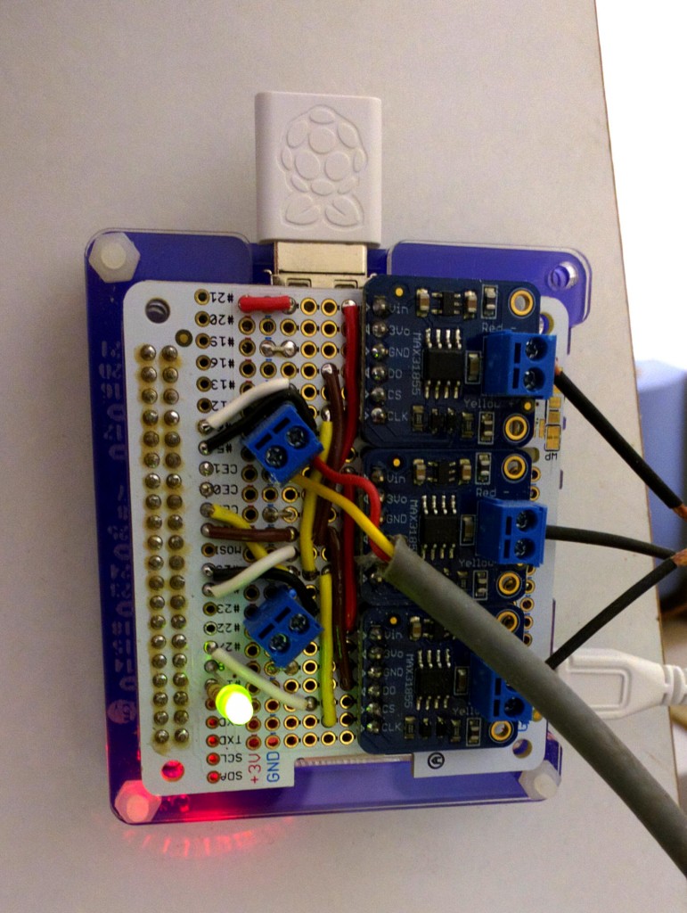
The big board that the Raspberry Pi sits on in the prototype weather station I have has an on-board 2-channel MCP3426 analog to digital converter. One channel is used to read the air quality sensor, the other reads the wind direction indicator. (The production model has 2 ADCs, but only uses one channel on each one).

wiringPi supports the MCP3422 (and 3424) ADCs so I decided to compare the data sheets for the ‘3422/4 and the ‘3426/7/8 … and I’ve found that with one small difference (the ‘3422 appears to support an 18-bit conversion) they are identical, so I don’t need to do anything here as long as I don’t try to use 18-bit mode on the MCP3426/7/8.

So lets test it.. Read both channels on the ADC:

$ gpio -x mcp3422:100:0x69:0:0 aread 100
2047
$ gpio -x mcp3422:100:0x69:0:0 aread 101
1188

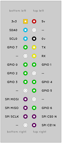
The syntax for using the MCP3422 here is that you need the pinBase (which you need for everything) this is 100 here, then the I2C address (0x69) then the sample rate (0 here is the default fastest to give 12 bits per sample) and the last 0 is the gain. 0 is no gain.

Reading channel 0 (pin 100 here) gives 2047. It looks like this input is pulled high…

The device can sample with 12, 14, 16 or 18 bit precision. The first zero in the command above selects the default which is 12 bits, but we’re reading 2047. This is 2^11 – 1… So why are we not seeing  then 2^12 -1 or 2047? It’s because the chip is designed to read the difference between 2 input pins and when used in single-ended mode (which it is here) you only get half the reading, so the range is 0 through 2047.

I’m guessing for now that channel 0 is connected to the wind direction device and that channel 1 is the air quality sensor… So I’ll plug in the wind direction thingy now and see what happens …

Wind direction

I ran the command:

$ while true; do gpio -x mcp3422:100:0x69:0:0 aread 100 ; done

and this printed the values up the screen in a stream which changed rapidly when I moved the wind direction indicator vane.

And so, yes, it’s verified to me that channel 0 is the wind direction indicator. These things are somewhat “creative” in their design in that they have a series of reed switches and a magnet. The switches are connected to resistors and its arranged in such a manner that you get 16 different voltage readings as the direction indicator turns.

See this page here for a good description of the wind direction indicator.

My task now is to work out each of the 16 direction readings and this my vary from system to system, so I might store it in a file for later use and tweaking…

Using the above script, I get the following reasonably unique values:

251, 814, 590, 1278, 969, 1763, 456, 100, 124, 46, 71, 23, 33

So I have 13 different values – not bad for 16 directions – however there was a lot of noise… Is it worthwhile trying to use these values I wonder … Digging a bit deeper, according to the data sheet, it should be possible to get 16 different readings for 16 directions. I am not seeing this at all.

Going to try again, but this time I’ll write some code to take the values and pass them through a low-pass filter to filter out the noise at the bottom bit and see what I get…

// vane.c:
//	Testing the Raspberry Pi Weather station wind vane

#include 
#include 
#include 

#define	DEPTH	8

int main (void)
{
  int filter [DEPTH] ;
  int i, p, value ;

  for (i = 0 ; i < DEPTH ; ++i)
    filter [i] = 0 ;

  wiringPiSetup () ;
  mcp3422Setup (100, 0x69, 0,0) ;

  for (;;)
  {
    filter [p] = analogRead (100) ;
    if (++p == DEPTH)
      p = 0 ;

    value = 0 ;
    for (i = 0 ; i < DEPTH ; ++i)
      value += filter [i] ;
    value /= DEPTH ;

    printf ("%6d\n", value) ;
    
  }
}

 I compiled it with:

gcc -Wall -o vane vane.c -lwiringPi -lm

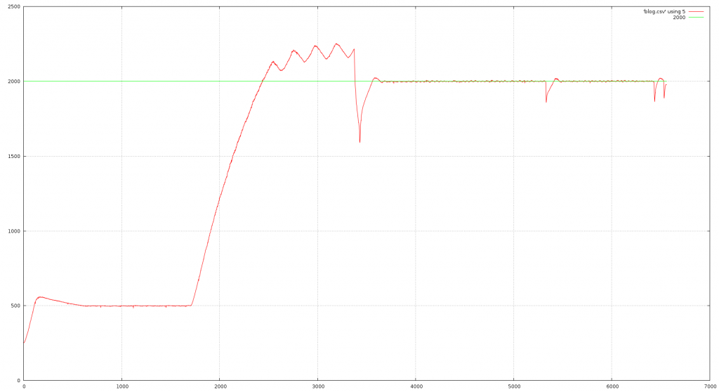
Running and I’m getting nice stable, steady readings… I’ve also aligned the device with the north mark pointing away from me and south pointing towards me, so when I install it, I’ll know what the values are once I align it with a compass.

Now I get:

  • 814 – This is North and it’s stable either side for about 1/8th of a turn.
  • then… 204,251, 29
  • 33 – East
  • then … 23, 71, 46
  • 124 – South
  • then … 100, 455, .. missing
  • 1765 is the best “west”
  • then … 1279, 590, missing
  • then back to 814 for north.

2 readings missing from the claimed 16. So it’s not perfect – the principle is good, but I fear the mechanicals and cheapness of the magnetic reed switches are letting it down here, however it will be good enough to group the readings together to give us 8 directions which is probably going to be sufficient for this little system.

Air Quality

The other input channel to the ADC is from the air quality sensor. This is a TGS 2600 device. It’s basically a tiny little heater, warming a little semiconductor element which is acting as a resistor whose resistance changes depending on the gas surrounding it. It’s sensitive to Methane, Carbon monoxide, Iso-Butane, Ethanol and Hydrogen. The higher the concentration of these gases the lower the resistance is. (so the higher the output) It’s somewhat basic, but may be useful for something.

I used the while true; gpio … loop above to check it. On plugging in, the value dropped slowly and stabilised after a minute or 3. I suspect this is the heater warming up. To test it, as it’s sensitive to butane I got my chefs blowtorch and gave it a squirt (no flame of-course!) the sensor maxed out to 2047 almost immediately and has stayed there for a couple of minutes now… And as I type this, it’s started to drop.

If you want to play with the sensor in another setting, then have a look at these good pages provided by that family friendly Raspberry Pi foundation…

Carbon monoxide is a killer gas, so this sensor has use in domestic situations especially where you may have solid fuel stoves – not uncommon in rural areas. It’s produced due to incomplete combustion and binds to your red blood cells more readily than Oxygen – but unlike Oxygen isn’t released, so you eventually pass out due to Oxygen starvation. You’re highly unlikely to ever encounter the concentrations required in the open though. However that and the other gases mentioned can be produced as by-products of pollution. The sensor is not going to be accurately calibrated so it’s only going to give fluctuations over time and not an absolute measure of those gases.

Next we’re on to the rain gauge and wind speed indicators…

Raspberry Pi Weather Station. 3 – 1-wire again

Following on from the weather station wiringPi page

So I’ve had a thought on the one-wire temperature sensor…. 1-Wire is a well defined system and works well on the Pi, however wiringPi has a “pin” based system, so how about adding it into wiringPi? Since I’d have to write the C code to parse the data file to present back to a program, then using that code in wiringPi as an analog input pin ought to be easy – right?

So from the “how hard can it be” department, I’ll embark on making the popular DS18B20 temperature sensors a wiringPi device…

A quick recap – when working, they appear in the /sys/bus/w1/devices directory. This is a virtual filesystem that dynamically changes depending on the 1-wire sensors/devices attached. Files are identified by a family-code prefix which identifys the device type and a serial number. This is a unique 64-bit number for every 1-wire device.

Checking my setup:

$ cat /sys/bus/w1/devices/28-0000053af458/w1_slave 
f6 00 4b 46 7f ff 0a 10 d6 : crc=d6 YES
f6 00 4b 46 7f ff 0a 10 d6 t=15375

So if I write a program to open that file, then read it in, all I need to do is scan for the “YES” which indicates a good read, then scan for the t= part to extract the temperature.

And done. Testing as usual by updating wpiExtensions.c and the Makefile, then running the gpio command and comparing with the direct file output:

$ gpio -x ds18b20:100:0000053af458 aread 100
166
$ cat /sys/bus/w1/devices/28-0000053af458/w1_slave 
09 01 4b 46 7f ff 07 10 bf : crc=bf YES
09 01 4b 46 7f ff 07 10 bf t=16562

And they both read just fine and my rounding seems OK too.

Back to earlier – “How hard can it be” – it was actually quite easy to implement this in wiringPi in C – afterall, the hard work has already been done in the OWFS (One Wire File System), so all I needed to do here was parse it. wiringPi could maintain 1000’s of these devices if required too (the limit is the number of open file handles – normally set at 1024, but can be trivially increased, if required)

Next on the list is tackling the analog to digital converter chip and seeing if we can make sense of the air quality sensor and wind direction indicator…

Raspberry Pi Weather Station. 2 – wiringPi

After setting up and testing some of the hardware in part 1, its now time to add the devices into wiringPi.

As in part 1, I’m writing this as I go, to give you an idea of my thoughts and a little more insight into the various processes I’m using.

wiringPi is a pin-based GPIO library. It has an abstraction layer that gives you a pin number that is then mapped onto the physical hardware, so rather than using e.g. bank 0, bit 17 you simply use “pin 0”, and so on for other pins. The Raspberry Pi does not bring out it’s usable GPIO pins in any sensible order and has in the past changed pins, so as long as wiringPi knows the internal mapping, then your programs don’t need to change or know what the hardware revision is.

wiringPi also supports the native pins and the board physical pin numbers should you wish to use them that way. This page has an explanation of the pin numbering history  The easiest way to get a full mapping of the pins on your Raspberry pi, just type gpio readall  This will work regardless of the Pi make, model or version you have.

e.g. on the Raspberry Pi B+ on the weather station I have:

$ gpio readall
 +-----+-----+---------+------+---+--B Plus--+---+------+---------+-----+-----+
 | BCM | wPi |   Name  | Mode | V | Physical | V | Mode | Name    | wPi | BCM |
 +-----+-----+---------+------+---+----++----+---+------+---------+-----+-----+
 |     |     |    3.3v |      |   |  1 || 2  |   |      | 5v      |     |     |
 |   2 |   8 |   SDA.1 | ALT0 | 1 |  3 || 4  |   |      | 5V      |     |     |
 |   3 |   9 |   SCL.1 | ALT0 | 1 |  5 || 6  |   |      | 0v      |     |     |
 |   4 |   7 | GPIO. 7 |   IN | 1 |  7 || 8  | 1 | ALT0 | TxD     | 15  | 14  |
 |     |     |      0v |      |   |  9 || 10 | 1 | ALT0 | RxD     | 16  | 15  |
 |  17 |   0 | GPIO. 0 |   IN | 0 | 11 || 12 | 0 | IN   | GPIO. 1 | 1   | 18  |
 |  27 |   2 | GPIO. 2 |   IN | 0 | 13 || 14 |   |      | 0v      |     |     |
 |  22 |   3 | GPIO. 3 |   IN | 0 | 15 || 16 | 0 | IN   | GPIO. 4 | 4   | 23  |
 |     |     |    3.3v |      |   | 17 || 18 | 0 | IN   | GPIO. 5 | 5   | 24  |
 |  10 |  12 |    MOSI |   IN | 0 | 19 || 20 |   |      | 0v      |     |     |
 |   9 |  13 |    MISO |   IN | 0 | 21 || 22 | 0 | IN   | GPIO. 6 | 6   | 25  |
 |  11 |  14 |    SCLK |   IN | 0 | 23 || 24 | 1 | IN   | CE0     | 10  | 8   |
 |     |     |      0v |      |   | 25 || 26 | 1 | IN   | CE1     | 11  | 7   |
 |   0 |  30 |   SDA.0 |   IN | 1 | 27 || 28 | 1 | IN   | SCL.0   | 31  | 1   |
 |   5 |  21 | GPIO.21 |   IN | 1 | 29 || 30 |   |      | 0v      |     |     |
 |   6 |  22 | GPIO.22 |   IN | 1 | 31 || 32 | 0 | IN   | GPIO.26 | 26  | 12  |
 |  13 |  23 | GPIO.23 |   IN | 0 | 33 || 34 |   |      | 0v      |     |     |
 |  19 |  24 | GPIO.24 |   IN | 0 | 35 || 36 | 0 | IN   | GPIO.27 | 27  | 16  |
 |  26 |  25 | GPIO.25 |   IN | 0 | 37 || 38 | 0 | IN   | GPIO.28 | 28  | 20  |
 |     |     |      0v |      |   | 39 || 40 | 0 | IN   | GPIO.29 | 29  | 21  |
 +-----+-----+---------+------+---+----++----+---+------+---------+-----+-----+
 | BCM | wPi |   Name  | Mode | V | Physical | V | Mode | Name    | wPi | BCM |
 +-----+-----+---------+------+---+--B Plus--+---+------+---------+-----+-----+

The middle column is the board physical pin numbers and working out from the middle to each side you have the pins value on a read (V), the current pin mode (input, output or one of the alternative modes – e.g. physical pins 3 and 5 are shown as ALT0 – this is the I2C mode), then there is the pin name – this is taken from various sources, e.g. GPIO numbers are from the original published document about the GPIO – and these are the same as the wiringPi pin numbers, then finally the native internal Broadcom pin numbers.

wiringPi is extensible in that you can add extra devices into it’s internal pin system and these devices can be digital or analog (or a combination of both). Internally there is a linked-list and when you ask for an operation on a pin that’s not internal to the Pi, wiringPi searches this list to find the driver code for the pin you are using then calls that driver code.

We need to add additional drivers for the humidity & temperature sensor (2 in one chip), and the pressure sensor, and then the analog to digital chip which has 2 connections; one to the air quality sensor and one to the wind direction indicator.

Lets start with the pressure sensor – the BMP180.

So google for the manual and I find that it has a temperature sensor as well as pressure. This isn’t unusual as it may be using the temperature as some sort of compensation for the pressure sensor. Page 11 of the manual has the sensor read flowchart.

So, since it can read pressure as well as temperature, let’s pretend this is a 2-pin analog input device. That way in our code we can simply

  temp = analogRead (base + 0) ;  press = analogRead (base + 1) ;

where base is the base pin we tell it to use when we initialise it.

Reading the manual more – it appears to be a register addressed device. It has a number of registers, each is 8-bits wide. There is calibration data which you read once then there is an algorithm which you follow to read and calculate the temperature and pressure.

More reading of the manual indicates that the BMP180 is the successor to the BMP085 and it just happens that I have code written for the BMP085, but not for the Raspberry Pi – it’s for an ATmega microcontroller system I did for someone else, so all I need to do it port the code…

But before that, we need to get the source code for wiringPi and understand how to build and install it and add stuff into it… But before that we really should un-install the packaged version…

$ sudo apt-get purge wiringpi
$ cd ~
$ git clone git://git.drogon.net/wiringPi

this failed as Raspbian Lite doesn’t have GIT installed, so:

$ sudo apt-get install git

then re-do the git clone operation above. (Note capitalisation here too)

to build and install wiringPi:

$ cd wiringPi
$ ./build

It will take a minute or 2 to complete. Test with:

$ which gpio
/usr/local/bin/gpio

and that should be it. Run gpio -v and gpio readall to make doubly sure.

Now for the BMP180 code. Start by copying something that’s similar. The pcf8591 is an I2C analog to digital converter device, so we’ll use that as a template.

$ cp pcf8591.c bmp180.c
$ cp pcf8581.h bmp180.h

and start editing the files… Not going to bore you with the details here the code will be in the next release of wiringPi, however some notes – the bmp180 has a lot of static calibration data. It’s inefficient to read it more than once, however the wiringPi device node structure doesn’t have enough space in it to store this data, so I could change the node structure, but this would waste space and require others to re-compile, or keep static data in the driver with the limit that only one BMP180 can be used in the system at any one time. I’m going to go with the latter limit for now… Which isn’t as bad as it might seem as the BMP180 has a fixed I2C address, so you can only use one per I2C bus – which really does mean one per Pi.

Makefiles

A Makefile is nothing more than a set of rules and actions. The rules are dependencies on files – or rather the last time a file was updated/created. If a file is deemed newer than the result of the action, then the action is performed.

It can be a lot more complex than that, but that’s the essence.

So why Makefiles? … wiringPi has 29 C files and a similar number of header files. If you change one of these files, then you really only need to compile that file – it’s a waste of file compiling all the files every time, so the Makefile lets you do that. It can scan the files, see while C source code files are newer than their corresponding object file, and if it finds such, then it can compile just that file, then perform a final linking operation. This lets you build large projects on relatively slow processors – such as the Raspberry Pi.

So – to add a new module into wiringPi, write the code, then update the Makefile to compile it, then it’s a matter of simply typing

make

and if that’s OK, then

sudo make install

to install the new library.

Are we there yet?

So this has taken me an hour or 2 – I started with my original code which I wrote for a microcontroller platform a few years back, then decided to see what else was about and a few google searches found a newer implementation for reading the BMP180 (and older BMP085) in a slightly more accurate manner, so I implemented it. The down-side of this code is that it requires the standard math library linking in to any programs that use it. In the process I added it into the Makefile and the wiringPi extensions system (see below) and used the existing gpio program to test it. Debugging? A few well placed printf statements when I needed them…

Testing

wiringPi has a utility program called simply gpio. It also has a run-time extension ability, so as I started to write the BMP180 code, I added it into the extensions facility – this is in the file wpiExtensions.c in the wiringPi directory. That way, I can call it from the gpio program without writing any more code (or re-compiling the gpio program)

$ gpio -x bmp180:100 aread 100
176
$ gpio -x bmp180:100 aread 101
10299

this tells the gpio program to use the bmp180 extension with a new pin base number of 100, then call the analog read function in that extension. (Reading pin 100 will read the first pin on the device. The bmp180 doesn’t have pins as such, but I’ve arranged the code such that reading pin 0 will read the temperature and return the temperature times 10. Reading pin 1 returns the pressure times 10 which is the absolute pressure in millibars and reading pin 2 returns the air pressure after compensation for your altitude – however you need to write to pin 0 to set your altitude in meters above sea level. It’s not really worth it unless you want high accuracy.

The gpio program is stateless, so trying to write the altitude isn’t going to do anything as it will be forgotten on the next gpio command execution. This can only be done within a program and will only be remembered for the duration of that programs run.

Incidentally, testing – is that the real temperature? I put the 1-wire sensor next to the air sensor board, left it a while then read them again:

$ cat /sys/bus/w1/devices/28-0000053af458/w1_slave 
08 01 4b 46 7f ff 08 10 e4 : crc=e4 YES
08 01 4b 46 7f ff 08 10 e4 t=16500

So the 1-wire sensor is telling me 16.5°C and the Bosch BMP180 sensor is telling me 17.6°C. That’s close enough to give me confidence that they’re either both totally wrong or reasonably right.

The other sensors

The other sensors on the Air board are the humidity sensor (which also has a temperature sensor) and the air quality sensor. The air quality sensor has an analog output so to make that work I need to write code for the ADC. The humidity sensor is the HTU21D device. It has registers but also supports direct reading. I’ll give it 2 “pins” just like the BMP180 – the first being to read its temperature sensor and the 2nd to read the relative humidity. There are different modes and resolutions that can be set, but I’ll leave it at its defaults.

The HTU21D

So I’ve basically copied the BMP180 code into htu21d.c, edited the wpiExtensions.c and Makefile then written the code for the HTU21D device.Like the BMP180, I am treating this chips as a 2-pin device and reading the first pin is the temperature and the 2nd pin gives the relative humidity.

Testing and it looks good – especially when I compare it to the bmp180 and the 1-wire sensor:

$ gpio -x htu21d:100 aread 100
162
$ gpio -x bmp180:100 aread 100
160
$ cat /sys/bus/w1/devices/28-0000053af458/w1_slave 
ee 00 4b 46 7f ff 02 10 de : crc=de YES
ee 00 4b 46 7f ff 02 10 de t=14875

So the HTU21D gives me 16.2°C, the BMP180 gives 16.0°C and the 1-wire sensor gives 14.9°C. All close enough to satisfy. (And yes, it’s a little chilly here today!)

Reading the humidity the same way:

$ gpio -x htu21d:100 aread 101
495

This represents 49.5% Relative humidity. Right now, I’ve no way of verifying this, but it’s in the right range and today is a crisp, cold, sunny and dry day, so it’s a plausible result. I did breathe on it and it went way up – probably not something to be recommended, but at least it’s changing in response to moisture. Putting it back on the floor where it’s currently living and it’s dropping again.

That’s enough for now. Next time I’ll look at the ADC and see if I can get something sensible out of the air quality sensor and the wind direction indicator.

Raspberry Pi Weather Station. 1 – Setup

The Raspberry Pi Weather station is a hardware and software system designed by the Raspberry Pi Foundation designed to let schools, etc. record their local weather. The system was produced in conjunction with Oracle who are providing a centralised database to allow all the stations to store data.

So… Some time back I was chatting with Dave Honess of the Foundation about what sensors, etc. to put on a weather station and Dave got down to the business of designing a prototype board. I was offered one, but it came at a time when I fell ill and didn’t have the capacity to do anything much with it at the time… However now I have some time to play, so after reading some posts on Raspberry Pi forums from people asking for some C tutorials with mention of the weather station, I have decided to use my system and get it going.

My aim is to use it as a demonstration to others how to go about tackling a project from the start. I will not be using any of the Pi Foundation supplied software, but will be re-implementing parts of it in C (and possibly BASIC) using the wiringPi GPIO library. This is not intended as a means to learn C from scratch, but may give newcomers to C some insight, tips and techniques. If I get round to a fancy local graphical thing then I’ll likely do that in BASIC as it’ll be easier than doing it in C (for me, anyway). I may leave it as an exercise to others to get the data generated back up to the centralised Oracle database…

I’m writing this as I do the tasks, so it’s a sort of log or journal as I go. My own thoughts and methods might not be to everyones tastes, but choice and difference is a good thing in general.

Let me note a few differences between the one I have and the production one. The prototype has a large PCB that the Pi sits on-top upside down – this is Pi on-top (POT!) rather than HArdware on Top (HAT). The large base has an on-board real-time clock (which I probably won’t use as it’s going to be connected to my LAN and use NTP), and an on-board ADC chip and 3 sockets marked “Air”, “Wind” and “Rain”. It has a wire soldered onto it which connects to a temperature sensor – designed to be buried in the soil to measure ground temperature. The production ones have the same hardware, but have the addition of a 2nd ADC chip which I think is to make the air quality sensor a little more reliable. (The ADC is next to it rather than at the end of a long cable) I just want to stress that this is a working prototype and not the productions ones currently in-use in schools, etc. however if anyone has one of the production ones and they want to re-implement the software this this should work for them and I’ll make notes of the differences where I can.

Starting up …

To start, I need to make sure it’s all actually working and I do this before I even think about writing a single line of code. There really is no point jumping in writing code unless you know the hardware is working correctly.

So – the Raspberry Pi. The unit that came with it is a Pi model B+ Rev. 1.2. As it was quite an old SD card image, I started by copying a fresh install of Raspbian Lite to the SD card, connected it to my LAN and powered it up.

I’m doing the install “headless”, so I found its IP address and used SSH from my Linux desktop computer to login with the usual pi/raspberry credentials. There are many tutorials for doing this elsewhere, so I won’t go into detail here.

Next, I did a full upgrade, (apt-get update && apt-get upgrade), removed packages I wasn’t interested in and fixed the network and init system to the way I like having them. (Linux gives me this choice and I use it) I used raspi-config to set the overclocking to “Medium” (900Mhz) and set the timezone to Europe/London. Again, there are tutorials elsewhere for doing this and a lot of this is personal preference anyway.

Raspbian Lite doesn’t have wiringPi installed, so…

$ sudo apt-get install wiringpi

Quick test:

$ gpio -v
gpio version: 2.32
Copyright (c) 2012-2015 Gordon Henderson
This is free software with ABSOLUTELY NO WARRANTY.
For details type: gpio -warranty

Raspberry Pi Details:
 Type: Model B+, Revision: 02, Memory: 512MB, Maker: Sony 
 * Device tree is enabled.
 * This Raspberry Pi supports user-level GPIO access.
 -> See the man-page for more details
 -> ie. export WIRINGPI_GPIOMEM=1

Looks good to me.

Sensors

Ready to start plugging things in and testing them now.

First thing I’ll test is the ground temperature probe. This is soldered to a wire on the base unit of the pre-production one I have. The sensor is a 1-Wire temperature probe, the DS18B20. Linux has good support for 1-wire devices, so all that needs to be done is make sure the 1-wire subsystem is enabled at boot time. Fortunately the weather station board is the new HAT style with an on-board configuration EEPROM, so it should just plug and go…

… however it looks like the EEPROM may not be programmed, or have old/incorrect data in it, as the 1-Wire interface doesn’t seem to be enabled at boot time. Running

$ sudo raspi-config

and selecting the 1-wire option allowed it to be enabled. Testing this is as simple as a few ls commands:

$ ls /sys/bus/w1/devices
28-0000053af458 w1_bus_master1

The file (it’s actually a directory) starting 28- is the one we’re interested in.  The 28 tells us this is a DS18B20 temperature device and the other numbers is its unique 64-bit serial number. This number will be different in your system as each chip has a unique serial number.

We can read the temperature by reading the w1_slave file in this directory…

$ cat /sys/bus/w1/devices/28-0000053af458/w1_slave 
01 01 4b 46 7f ff 0f 10 e3 : crc=e3 YES
01 01 4b 46 7f ff 0f 10 e3 t=16062

We’re interested in 2 bits of information here – the first is the YES which means the device read successfully, the second is the t=16062. This is the temperature in °C times 1000, so it’s reading 16.062°C, however do not for one minute think that this sensor is any more accurate than 0.5°C. It’s not, so round appropriately when reading – ie. the temperature here is really 16.1°C give or take half a degree.

So what next. The air  sensors, I think. These are I2C devices on a separate board. Plugging it all together and I find that I need to install the i2c-tools package, then use raspi-config to enable the I2C system.

The wiringPi gpio command has a shortcut to the i2cdetect command and running it gives:

$ gpio i2cd
     0  1  2  3  4  5  6  7  8  9  a  b  c  d  e  f
00:          -- -- -- -- -- -- -- -- -- -- -- -- -- 
10: -- -- -- -- -- -- -- -- -- -- -- -- -- -- -- -- 
20: -- -- -- -- -- -- -- -- -- -- -- -- -- -- -- -- 
30: -- -- -- -- -- -- -- -- -- -- -- -- -- -- -- -- 
40: -- -- -- -- -- -- -- -- -- -- -- -- -- -- -- -- 
50: -- -- -- -- -- -- -- -- -- -- -- -- -- -- -- -- 
60: -- -- -- -- -- -- -- -- 68 69 -- -- -- -- -- -- 
70: -- -- -- -- -- -- -- --

Which is a little concerning as there are 3 devices on the Air Sensor board… Further investigation suggests that the board isn’t being read at all and those 2 devices are the main boards RTC and the analog to digital converter.

It’s possible that the cable I’m using isn’t the right one, or its too long.

  • … And an hour or so passes and I’ve found the right cable and learned a little more about the system. I initially thought the air quality sensor was I2C, it’s not; it’s analog. My output is now:
     0  1  2  3  4  5  6  7  8  9  a  b  c  d  e  f
00:          -- -- -- -- -- -- -- -- -- -- -- -- -- 
10: -- -- -- -- -- -- -- -- -- -- -- -- -- -- -- -- 
20: -- -- -- -- -- -- -- -- -- -- -- -- -- -- -- -- 
30: -- -- -- -- -- -- -- -- -- -- -- -- -- -- -- -- 
40: 40 -- -- -- -- -- -- -- -- -- -- -- -- -- -- -- 
50: -- -- -- -- -- -- -- -- -- -- -- -- -- -- -- -- 
60: -- -- -- -- -- -- -- -- 68 69 -- -- -- -- -- -- 
70: -- -- -- -- -- -- -- 77

and the devices are:

  • 40: HTU21D – Combined humidity and temperature sensor.
  • 68: The RTC
  • 69: MCP3427 2-channel ADC (The production board has 2 of these and on those boards you’ll see an extra 6A. My prototype board only has one).
  • 77: BMP180 – Barometric air pressure sensor.

The 2-channel ADC chip has inputs from the air quality sensor and from the wind direction sensor. The rain and wind speed sensors are connected directly to GPIO pins.

And that’s enough for part 1. I’ve setup the Pi, identified the hardware, plugged some of it in and while not reading all the sensors at least made sure that the I2C devices are all present.

wiringPi doesn’t have drivers for any of these sensor chips so the next stage will be to write code for the (in C) and test them.

Next time we’ll get the wiringPi source, write new devices for wiringPi, update the Makefile and do some testing.

wiringPi Pin numbering

I’m asked many times why wiringPi has its own pin numbering scheme for the Raspberry Pi, rather than use the native hardware pin numbering (which is can also use, along with the physical pin numbers)..

The answers are simple…

  • Firstly… In the very first published diagram of the GPIO connector on the eLinux wiki site the user-usable GPIO pins were numbered zero through seven. So I thought that was fine and I added mappings into wiringPi to make them do just this – after all, in any program you could now run  simple loop from 0 to 7 to access all pins – e.g. to light up 8 LEDs. (Note that this diagram has since been re-drawn and no-longer numbers them from 0 to 7)
  • Secondly… To try to encourage Arduino users over to the Pi – wiringPi makes it somewhat easy here too. In Arduino land, we don’t talk about port C, bit 7, we talk about “pin 13” (and in almost All Arduinos “pin 13” is the notification LED – the ones you use for your very first “blink” program – the underlying Arduino wiring library hides the actual hardware port and bits from you).
  • Continuing on… When the Pi hardware was changed, the foundation re-provisioned 3 pins on the original 26-way connector. If you stuck to wiringPi pin numbers you were fine and you didn’t need to change your programs as the pins numbers didn’t change, but if you were using the native pin numbers, then you needed to work out what board revision you are using, then re-map the pins in your own code.

So there you have it. That’s why wiringPi has 3 pin numbering modes. Please read the fine manual for the ways to use each mode.

Original GPIO pin diagram:

This is a copy of the first GPIO pinout diagram. It was published on the elinux.org wiki site on the 13th March, 2012. This is what I originally based my wiringPi pin numbers on.

gpiosThe original is here

A rude awakening

So early evening last night (Saturday 19th Match), a nearby neighbours power went off… They called Western Power who at about 9pm decided that it was an emergency… Due to a young person being in the affected house.

So at about 1:45am, Sunday morning a crew from Keir turned up and started digging with power tools.

This more or less woke up the whole street. Several neighbours went outside to complain, but the workmen were somewhat non-caring and carried on making a noise. They kept on making a noise for about an hour or so before leaving.

So no-one in the street got much sleep.

The worst part? They didn’t need to dig at all. Upon inspection to see what they’d done, I found none of their digging was directly connected with restoring the power to the affected house. To fix their power, they ran a temporary cable from a street-side junction box into the house through their letter box (and presumably into their consumer unit)

power3This is the view down the street. The barriers at the right is where the power cable is tapped into:

power1This is the power tap – the cable went down the street into the house:

power2Let there be power!

The proper fix has started at about 5pm on Sunday afternoon. More people from Western Power and Keir have turned up. It’s now nearly 7pm and they’re still digging.

power4Mini digger and operator hard at work…

It has been a fairly tiring time here. Who knows how much longer they’ll go on. Worse – the questions I’m asking is why? Why did they have to dig this up at 2am on Sunday morning? Why are they now digging at 7pm? Why couldn’t they have run the temporary cable and left it until Monday?

I think it’s fair to say that Western Power and their contractors are not the best loved people here tonight.

Raspberry Pi v3

On the first birthday of the Raspberry Pi (That’s the first anniversary of the original February 29th launch!) The fantastic foundation brings out the Model B v3.

Features over and above the existing Pi Model B v2:

  • Wi-Fi and Bluetooth (Bluetooth Low Energy/BLE)
  • Upgraded power handling – capable of handling 2.5 amps at 5v over the board. You need a good PSU then you can run lots of USB and GPIO things.
  • 1.2Ghz (fixed, not OC for now)
  • 64-bit ARM v8.
  • $35 – around £26 to £27 in the UK.

Physically it’s the same size, same mounting holes, GPIO connector, etc. as the B+ and v2. The only obvious difference is the location of the LEDs. However a quick test shows that the LEDs will show through the side of the official Pi case and most of the ones with transparent lids and sides won’t be an issue either (e.g. Pimoroni Coupé case)

Images

Here it is next to a Model B v2 for comparison. The v3 is the one on the left

pi23A quick glance doesn’t show anything much, but look to the top-right of the board – the LEDs on the v2 have been moved to the top-left of the v3 board on the v3 and in their place on the v3 is the chip antennae for the Wi-Fi and Bluetooth interface. (The support ICs, etc. for that are underneath the board)

More details on the new features

Power

The on-board power distribution can handle up to 2.5 amps at 5v now and USB power control has been dropped – it’s fixed at 1.2 amps, so make sure you have a good PSU capable of delivering over 2 amps if you want to make full use of it – I did a test and had 4 other Raspberry Pi’s being powered off the USB ports.

USB over current detection is still present and will show up in the logs should you exceeded the overall 1.2 amp limit.

Wi-Fi

The Wi-Fi is not connected to the existing USB interface. It’s on an interface of it’s own – It is using the SDIO interface via the GPIO so it won’t use any precious USB bandwidth. This should improve performance for those using the Pi as a Wi-Fi access point, if nothing else.

Some quick benchmarks have shown speeds of 40Mb/sec via Wi-Fi.

Bluetooth Low Energy

The BLE interface runs off one of the Pi’s serial ports. It has 2 serial ports and only one has been exposed via the GPIO previously. I understand it’s actually running off the original one, which is now using the secondary, but some internal munging has happened to keep that as /dev/ttyAMA0 for user applications.

64-bit

Raspbian hasn’t yet been updated to make use of the 64-bit cores… Give it time.

Misc. details

In some informal chats with the boffins at Pi HQ they mention running out of GPIO pins used for the Wi-Fi and BLE interfaces, and so the LEDs and under-voltage signal, etc. are on a separate GPIO expander controlled by the GPU. There is no USB power control it’s now fixed at 1.2A. I’ll try to clarify this when they manage to get some spare time to breathe after the work required to get this to product!

wiringPi

wiringPi has been updated and it will be available via apt-get/update shortly, but for now you can get it directly via the downloads method on the wiringPi website.

And well that’s that! Happy Birthday Raspberry Pi. And still for $35 too.

Raspberry Pi controlled Oven

So as well as technology, I love baking – to the extent that I bake stuff to sell with all the shenanigans that goes with that. Local authority inspections, food hygiene certificates, insurance, blah….

Some bread I made … (Devon Honey Spelt if interested)

And then one day I foolishly thought it might be  good idea to combine my love of geekery and technology with my love of baking… And stuck a Raspberry Pi to the side of one of my ovens. I did have a couple of reasons to do it (other than because I can) one is to cook meringues at a cool 60°C and another is to bake some bread that requires a gently cooling oven from about 200°C to about 100°C over a period of about 6-10 hours. I’ve not done that yet, but it’s on the cards. Meanwhile…

Here it is:

ovenPiSo that’s an A+ model in a nice Pimoroni case with an Adafruit perma proto-plate on-top with some “stuff” to control the oven stuck on the side of the oven with some Blu-Tack for now. It’s powered up – stays online all the time now (I had issues with an old Wi-Fi dongle, replaced it with one of the Foundation approved ones and it’s been rock-solid since then). The three thin  cables go to thermocouples inside the oven compartment and the grey cable goes to a SSR (Solid State Relay) inside the top of the oven. The Green LED is actually a bi-colour LED wired across 2 GPIO pins with a resistor. It can be off, green, red or if I could be bothered to write code to alternate the pins, a sort of muddy yellow. I just use it to indicate the heater being on (red) or off (green).

So how do you control an oven? Lets break it down into steps. One thing I was interested in was just how rubbish my oven really was. I already knew where the hot spots were (the bottom of the oven is hotter than the top – who’d have thought that?) and how unevenly it cooked as well as just how approximate the temperature dial was (plus or minus a fruit cake) so the first task was to measure the temperatures. Most of the temperature sensors you see people plugging into the Pi are only good to about 120°C or thereabouts. I wanted something that was good to 300°C or more. (This oven maxes out at 250, but I have others that go to 300…)

Thermocouples are the ideal thing here, but they’re somewhat different from your usual semiconductor sensor. They work by exploiting the fact that when you put 2 different metals next to each other they will generate a voltage. A tiny voltage, but a voltage none the less. It also turns out that the voltage varys in a reasonably linear way according to the temperature. So all we need is to plug the thermocouple into a suitable amplifier, digitise the result and read it into the Pi. This is somewhat simplified and you’ll hear people bleat on about “cold junction compensation” blah, blah blah, and other stuff, but the trick here is to use a chip that does all that for you. The MAX31855 is such a chip and Adafruit have a neat little breakout board which has the chip on a breakout board with terminals for the sensor and pins to hook up the digital side. Being based in the UK, I bought them from a UK distributor of Adafruit products, SKPang along with some Type K thermocouples. (Thermocouples come in different types depending on the materials used and so-on).

So after testing these and fixing the wiringPi max31855 driver I soldered some onto an Adafruit perma proto-plate and tested it.

Now here’s a little problem – I wanted to use three thermocouples. Great. The MAX31855 is an SPI device. Also great. The Pi only has 2 SPI channels. Not so great. Ah well. My solution was to use 3 other ordinary GPIO pins as the CE lines to the 3 devices. This works well.

So why three sensors? Initially I was interested in just how bad the oven temperature varies over the interior, then I thought about redundancy – and here’s an issue: Confucius says: “Man with one thermometer knows exact temperature. Man with 2, never sure …” Well, maybe he didn’t, but you know what I mean. Fortunately there are some fairly standard ways of dealing with this. One way is a simple “voting logic” approach. You read the sensors and you pick the 2 that are closest then average those 2 to get the temperature. You also apply some heuristics to check the third sensor to see just how far away from the average it is – and can then use that information to print an error message if it goes too far away, or just log it for another day.

This worked well, but it wasn’t without problems – when the oven got to a stable temperature, the odd-sensor-out changed and the resulting 2 sensor average jumped a little – not much, but enough to cause some issues with the control loop. In the end I dropped it and just averaged all three sensors and built in some heuristics to check for a sensor going too far off-course. This works well. There are other algorithms to read and sense and generate the oven temperature, but for a little hobby project this is good enough for now.

So I started to produce graphs using the existing mechanical/capillary tube sensor. These sensors work by having a sealed tube and a sensor with a spring behind it. The power of the spring is determined by the rotary knob. When the sensor pushed hard enough the switch inside the knob clicks and the heater turns off…. Until it cools down a little, then the oven turns back on again and the process repeats for the duration.

This is how the majority of domestic (and some commercial!) ovens work. It’s a somewhat crude system, but it’s tried and tested and been in-use for decades.

So just how crude? Here is a graph:

ovenRunThis is a single run of the oven. Y Axis is temperature in °C * 10 and the X axis is time in second.

I started with the Pi set to 50°C and ran it for for time (half an hour or so) then I used the ovens mechanical controller to take it to 200°C … As you see it’s somewhat hotter than 200 and lots of wibbly wobbly temperature swings. After 20 minutes of this, I turned the ovens controller to zero and opened the door for a few minutes, then told the Pi to control it to 200°C and closed the door. It gets up to 200°C fairly quickly, overshoots by a degree or 2, then settles down – it’s better than +/- 1°C at that point.

The next little dip is when I opened the door to load up a tray of mince pies – well it is Christmas time after all.. There is another dip about 15 minutes later when I opened the door to turn the tray, then a couple of minutes after that when I took the tray out and turned it all off.

mincePieOne of the mince pies that it cooked during that run.

Read more about my thoughts on mince pies here …

After initially measuring the temperatures and being somewhat surprised at just how crude (and inaccurate) the existing controller was, the next step was to control the oven. The oven heater is 2.2Kw and 230v, so this isn’t really anything you want to fiddle with unless you are 100% confident you know what you’re doing. My background from 25+ years back was factory automation, designing & building robotic transfer mechanisms, controlling machine tools and so on. I’m comfortable with my ability to control stuff like that, so controlling a simple heater ought to be relatively easy.

And it is. But DO NOT try this yourself unless you are fully confident of you own ability. I will not present any photos of what my system looks like inside the oven – if you want to do this, then you are on your own, however I will write about what I used and how I did it, but no code, sorry. (It’s written in BASIC, anyway)

I chose an off-the-shelf SSR (solid state relay) unit. I went for a 40 amp device with heatsink. These devices have been about for a very long time and are not that efficient and dropping 2v at 10 amps is a power loss of 20 watts which you have to get rid off – inside an already warm cavity above the oven chamber. The heatsink is bolted to the frame of the oven and the high voltage terminals wired across the existing thermostat switch. This makes it simple to use – and with the Pi turned off I can still use the existing thermostat.

The low voltage side of the SSR is connected directly to the Pi. This is nothing more than a resistor and LED (inside the SSR) so all the Pi has to so is provide 3.3v and a few milliamps to turn of the LED that forms part of the opto isolator inside the SSR.

An advantage of the SSR I used was zero crossing detection. Simply put the thing only turns on or off when he mains cycle crosses zero – either way up or down. The advantage of that is that it vastly reduces electrical noise. No clicks on nearby radios. A side effect of that is limiting the minimum time I can turn the power on for – one half cycle or (at the UKs 50Hz) a 100th of a second. In practice this isn’t an issue as the minimum time I’m going to turn the heater on for is in the order of 1/10th of a second.

More on safety

The oven has a built-in over temperature cut-out and additionally has a simple mechanical timer. I use the timer – wind it up to 100 minutes so that if the worst were to happen and it did overheat and the cut-out didn’t trip, then hopefully for no more than that time.

Now there’s just the little issue of controlling the oven temperature… There are many standard algorithms but the usual one is often called PID or three-term controller. PID stands for Proportional (multiply the error by a constant to get the new output), Integral (looks at the magnitude and duration of the error) and Derivative (look at the rate of change of the error). The error here is the difference in measured temperature against the desired temperature. There is some interesting calculus to execute the PID control, but in a program its really only 3 lines of code.

A down-side is that a PID algorithm needs to be tuned. There are several standard ways to tune the algorithm – most involve sitting down and working through the parameters, tweaking one at a time and checking the graphs and there are some auto-tune algorithms too. I adapted an auto-tune algorithm, but it didn’t work very well, so I sat down and made a few approximations to the tuning parameters then tweaked them after a few real runs. It’s not yet perfect, but more than good enough to bake a sponge cake. Currently it overshoots by a degree or 2 (this is more apparent at lower temperatures) but it isn’t an issue whatsoever.

I suppose some of you are still asking: Why? And the answer is because it’s fun and because I can.

Look out for another exciting episode of my Pi controlled oven when I’ll be doing a video and showing you how to make a simple loaf of bread…

4 Pi’s on my screen… What?

4pisA quad-core Raspberry Pi?

Sure. Why not. Put 4 x ARMv7 Cortex-A4 cores on the chip and lets give it 1GB of RAM while we’re at it.

pi2And here it is. The Pi v2.

Unlike all previous Raspberry Pi’s the memory chip is now on the reverse, but otherwise this Pi is exactly the same layout as the current B+ so all your old (and new!) cases remain the same.

So is it faster? You bet… A simple benchmark:

Compile my RTB BASIC interpreter – on a B+ it takes nearly 3 minutes from scratch. In the Pi 2 using a single core that compile time drops to 1 minute and 9 seconds. Using all 4 cores, the compile time drops to a mere 21 seconds! That’s nearly NINE times faster than an existing Pi! Obviously not everything will go faster, and to make full use of that speed, you’ll need to write programs that are multi-threaded – no easy task, but the potential is there.

Want to see /proc/cpuinfo? Here it is:

processor : 0
model name : ARMv7 Processor rev 5 (v7l)
Features : half thumb fastmult vfp edsp vfpv3 tls vfpv4 idiva idivt vfpd32 lpae evtstrm 
CPU implementer : 0x41
CPU architecture: 7
CPU variant : 0x0
CPU part : 0xc07
CPU revision : 5

processor : 1
model name : ARMv7 Processor rev 5 (v7l)
Features : half thumb fastmult vfp edsp vfpv3 tls vfpv4 idiva idivt vfpd32 lpae evtstrm 
CPU implementer : 0x41
CPU architecture: 7
CPU variant : 0x0
CPU part : 0xc07
CPU revision : 5

processor : 2
model name : ARMv7 Processor rev 5 (v7l)
Features : half thumb fastmult vfp edsp vfpv3 tls vfpv4 idiva idivt vfpd32 lpae evtstrm 
CPU implementer : 0x41
CPU architecture: 7
CPU variant : 0x0
CPU part : 0xc07
CPU revision : 5

processor : 3
model name : ARMv7 Processor rev 5 (v7l)
Features : half thumb fastmult vfp edsp vfpv3 tls vfpv4 idiva idivt vfpd32 lpae evtstrm 
CPU implementer : 0x41
CPU architecture: 7
CPU variant : 0x0
CPU part : 0xc07
CPU revision : 5

Hardware : BCM2708
Revision : 0010
Serial : 000000000884752a

And here are the first few lines of ‘top’ while I’m at it: (Press ‘1’ to get the CPU lines if trying this yourself)

top - 22:58:18 up 19 min, 1 user, load average: 0.00, 0.06, 0.06
Tasks: 74 total, 1 running, 73 sleeping, 0 stopped, 0 zombie
%Cpu0 : 0.0 us, 0.0 sy, 0.0 ni,100.0 id, 0.0 wa, 0.0 hi, 0.0 si, 0.0 st
%Cpu1 : 0.0 us, 0.0 sy, 0.0 ni,100.0 id, 0.0 wa, 0.0 hi, 0.0 si, 0.0 st
%Cpu2 : 0.0 us, 0.3 sy, 0.0 ni, 99.7 id, 0.0 wa, 0.0 hi, 0.0 si, 0.0 st
%Cpu3 : 0.0 us, 0.0 sy, 0.0 ni,100.0 id, 0.0 wa, 0.0 hi, 0.0 si, 0.0 st
KiB Mem: 764060 total, 76048 used, 688012 free, 9964 buffers
KiB Swap: 102396 total, 0 used, 102396 free, 40072 cached

In brief

This is the Raspberry Pi you’ve all been waiting for – and I know a lot of people will be saying it’s the Raspberry Pi that should have been three years ago, but you have to start somewhere. I do not believe this could have been possible without all the existing sales and support over the past few years. Proof, in anyone needed it that there is a need for a computer like this. A computer that can help develop and nurture the next generation of computer scientists, programmers and day to day users, just as the micros of the 70’s and 80’s did for us older folks.

Well done to everyone at the Raspberry Pi foundation! What a fantastic addition to the family.

GPIO

And before I forget it – a HUGE thanks to Eben and the Foundation for allowing me a sneak peak of the Pi v2 so I can make sure my wiringPi librarys work on the v2.

The GPIO is the same as before, however the peripheral base address has changed and wiringPi has been updated to reflect this change. Please fetch a new version of wiringPi (make sure you have version 2.24) and off you go. It auto-detects which Pi you’re on and does the right thing.

And on the 49th day, it stopped…

I’ve had two people recently email me regarding their Raspberry Pi sensor monitoring projects stop after 49 days… The reason is simple, the solution slightly more complex, so what’s going on?

The wiringPi GPIO library has a function: millis() which returns an unsigned 32-bit integer representing the number of milliseconds since your program started (or more accurately since your program last called one of the wiringPiSetup() functions). A few quick sums demonstrates that this counter wraps round after about 49 days, so programs that naively add a fixed number into the result of millis() to get the next time then test millis() > nextTime  will fail after 49 days…

And for at least one case, I’m the guilty one here – in my maxdetect code (used for the rht03 and similar sensors) I use millis() to make sure the next time we access the hardware is inside the datasheet limits. (The datasheet suggests not reading more than once every 2 seconds).

It’s easy to pass blame and not have any idea what’s going on – C for example doesn’t flag any warnings of integer overflow for example… However solutions to integer overflow problems are well understood and not complex.

So I’m working on a fix to the maxdetect code (which needs re-writing anyway), but if you’re using millis() in your own application, and it stops after 49 days, then now you know why!

And a quick note to say – uptime – 49 days – who says the Raspberry Pi isn’t reliable, but others should note that this issue is applicable to Adruinos and other microcontrollers too! More-so if you are using the micros() function which wraps after 71 minutes!