Testing & Setting the USB current limiter on the Raspberry Pi B+

One of the features of the new Raspberry Pi B+ is improved power handling – particularly round the USB interfaces. There is a device connected to the power to the USB ports that is quite clever – it controls the power and “soft starts” the peripherals plugged in. This helps to reduce any brown-outs on the main Pi supply, so reducing the chance of the Pi rebooting when you plug in a USB peripheral with the Pi turned on.

Additionally, it can also limit the total current drawn by the USB peripherals. This is 600mA by default, but can be increased to 1.2A via software.

Warning: DO NOT do this on a whim. Only do this if you are absolutely sure that you need to do it!

But if you do need it, then “How?” I hear you ask… Well, simple… There are 2 ways.

The first way is via a new option in /boot/config.txt. Currently you can add:

safe_mode_gpio=4

but note that this will become:

max_usb_current=1

in subsequent updates. To do that requires a reboot of your Pi, however there is a 2nd way and that’s in software – because the actual switch is controlled via the Pi’s GPIO, we can do it from the command-line after the Pi has booted:

BCM_GPIO pin number 38 is the magic control pin.

Using the wiringPi gpio command, you can do the following:

gpio -g write 38 0
gpio -g mode 38 out

You may think I’m doing this the wrong way round, but you want to make sure you’re not switching it high accidentally, so we make sure the output is going to be low when we force the pin to output mode, and low (or 0) is the default 600mA limit.

To increase the limit to 1.2A:

gpio -g write 38 1

The next version of wiringPi will feature a built-in function of the gpio command to read and set the USB current limiter, but for now, if you need to set it high, then that’s what you can do.

And as always please make sure you use a good quality power supply for your Pi! I’ve seen more problems caused by people using cheap wall-warts that can barely power a Pi, let alone any USB peripherals.

My test rig for this involved getting my B+ to power 2 other Pi’s via the USB ports on the B+. With the default 600mA setting, the Pi’s would not boot – they powered up, tripped the limiter which powered them down again for a second or 2, then the process repeated. With the limit set to 1.2A they both powered up and booted at the same time without a hitch.

I really don’t recommend you do this – or if you do something similar, don’t let it run too long. Also, keep an eye on the Red power LED – if you see this flickering it means that something is causing the power supply to “brown out”. Hopefully not enough to reboot the Pi, but it’s something to watch out for when you plug USB peripherals in

b+powerExcuse the somewhat chaotic nature of this photo – just trying to cram everything in. The B+ is being powered by an Anker 15,000mAh USB battery charger unit – it was the first 2A PSU I had to hand … Works a treat!

A quick look at the new Raspberry Pi model B+

Much excitement here at Drogon towers as I have a new Raspberry Pi – the model B+

b+

So what’s a B+ and how does it differ from the B? Here is a quick list of the main differences:

  • USB: 4 ports instead of 2
  • USB Power limiting – switchable from 600mA to 1.2A.
  • GPIO: 26 usable pins instead of 17 (21 on the Rev 2)
  • GPIO: No “P5/P6” connector that was present on the model B.
  • Composite video routed via the 3.5mm jack used for audio.
  • Micro SD card.
  • Round corners on the PCB!
  • Proper mounting holes.
  • Improved power supply – 2 amp polyfuse on the input and SMPS 3.3 and 1.8v generators to replace the linear ones on the existing Pi, along with some new widgetry round the audio output to improve the signal there. It saves up to 1 watt according to the boffins at Pi HQ!
  • Low power indicator.

Those are the main differences as far as most people will be concerned. The combined composite video and audio is (I understand!) a popular connection on phones, tablets, etc. The same HDMI, CSI (Camera) and DSI (Display) ports as the current Model B.

The power is an area of big improvement – I’m told the routing on the board is much improved with more power available to the USB sockets – providing your power supply is capable (please buy a good PSU from a reputable dealer!) Also, the USB sockets have been blocked from “back-powering” the rest of the Pi – presumably to prevent any issues with external powered hubs and so on.

The low voltage indicator will turn the power LED OFF if the supply voltage is lower than 4.7 volts. Buy good quality power supplies!

A quick note on the GPIO: There are actually 2 more pins in the connector – the original I2C bus that appeared on the Revision 1 boards, however this comes with a warning that the bootloader actively probes them, looking for an I2C eeprom device, to be used for further configuration by the bootloader, so connecting anything to them is not advised.

Notes:

wiringPi has been updated to reflect the new board revision in /proc/cpuinfo (currently it reads 0010).

Software: Well, no change there, really. Same SoC/CPU and memory, so no changes, really.

GPIO: The additional GPIO pins can be used for:  PWM (Both channels!) and additional GPIO clocks. Access to the 4 PCM signals is also possible, so I2S is easy to access, so lack of the P5/P6 connector on the model B shouldn’t be an issue.

On the GPIO front – the Ethernet socket is a few mm back into the board which may affect the positioning of some GPIO add-on boards that are wide enough to touch the Ethernet socket.

Conclusion

I think it’s a great and logical progression to the Pi! It’s compatible software and hardware wise – most existing GPIO devices will plug right on-top (may have to wiggle a ribbon cable in though for e.g. my original ladder board, the Gertboard, “cobbler cable” any anything else that uses a ribbon cable, but most of the boards I have which sit on-top all seem to fit and work just fine. (A notable exception is the PiFace board which was designed to fit round the Ethernet and USB sockets) More GPIO pins are always going to be good, and you can never have enough USB ports (Get a good power supply!)

And to finish, here is a photo of the B and B+ next to each other: They’re in the new Pimoroni Coupé cases. Excellent cases – protects the Pi and lets you use the GPIO to place boards on-top.

b-b+Note the GPIO pin numbers (BCM format) are given on the case top. Really handy!

And just because I can – here is the Pi driving 28 LEDs:

pi28ledsYes, I know. Don’t draw more than 50mA through to SoC, and there are 2 pins there that I really shouldn’t use (the first I2C bus), but hey, there it is!


LMC – The Little Man Computer on the Raspberry Pi

From the Wikipedia entry:

The Little Man Computer (LMC) is an instructional model of a computer, created by Dr. Stuart Madnick in 1965. The LMC is generally used to teach students, because it models a simple von Neumann architecture computer – which has all of the basic features of a modern computer. It can be programmed in machine code (albeit in decimal rather than binary) or assembly code.

This implementation is written using RTB on the Raspberry Pi and allows manual data entry via the computer control panel or you can use the built-in assembler to load files in its assembly language.

I have added some extensions to LMC to modernise it from its 1965 roots. The first is the JSR and RET instructions. JSR is Jump to Subroutine and RET is return. In keeping with the simplicity of the system, there is only one register to store the program counter for the RET address.  The other additions are for the Raspberry Pi’s GPIO. You can read a pin or set a pin to high or low. See the examples for details.

The RTB/Raspberry Pi implementation features three running modes – one is slow and runs at 10 instructions per second. This allows you to visually see the memory and accumulator changing as well as the program flow, the second is fast mode – the output register is updated, but that’s all, and finally you can single-step a program.

Download and Install

First you need RTB installing on your Raspberry Pi. See here for full details.

Obtaining the LMC software and examples:

cd
git clone git://git.drogon.net/lmc

that will create a directory called lmc and download the code and examples into it. Once that’s complere you can start rtb and load the code and off you go:

cd lmc
rtb

(then inside RTB)

load lmc
run

And you should see the main computer screen:

lmc
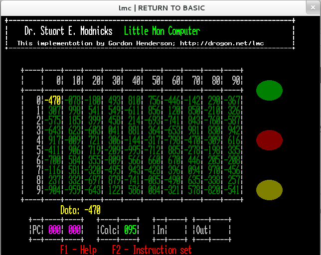
The main memory array is in the middle (full of random numbers at start time), the indicators on the right are Run (Green), Error (Red) and Input (Yellow). All are shown in their “off” state here.

The Yellow number and text in the middle is the current instruction or data that the program counter is pointing to and the bottom four boxes contain the program counter and saved program counter values, the calculator (accumulator) and the input and output registers.

When the program is running in slow-mode, the current instruction is highlighted in Pink with the disassembly also in Pink.

lmc2
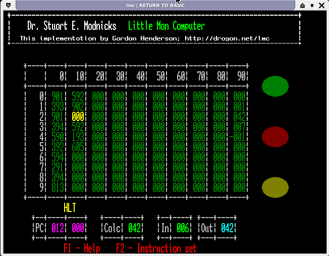
This is the LMC screen at the end of a run of the multiply.lmc program when asked to multiply 6 by 7.

Operation

The LMC is controlled by simple key-presses. On the main screen, you can move the active location (memory address highlighted in Yellow) using the arrow keys. To manually enter data or an instruction just type the numbers – the memory locations will only take the last 3 digits typed. Entering 1234 will result in 234 being placed into the memory location. Use the minus key (-) to negate the value. Pressing the Enter key moves to the next memory location.

Note some commands are case-sensitive.

  • Z (Capital Z) Zeros the computer.
  • R (Capital R) Runs the program from location 0 at full speed. Only the output register is updated in this mode.
  • r (Lower case r) Runs the program from location 0 in slow mode. This is a rate of 10 instructions per second with the display being dynamically updated as the program runs.
  • S (Upper or lower case) Single-Steps the program from the current program counter. (ie. if you need to start it at location zero, then you need to move the highlighted location to zero first)
  • L (Upper or lower case) loads in a new assembly program (ie. with mnemonics, not binary code!)
  • A (Upper or lower case) Assembles the previously loaded program into  the numerical form and stores it in the LMC memory.

The reason there are separate Load and Assemble commands is because a running program may alter its data, so a 2nd run of the same program may start off with the wrong values unless you write additional code to correctly initialise a location, or separate locations containing constants and variables. With the separate commands here, you can load a program once, assemble and run it many times.

So typically, you would load a program once (L command), Zero the memory (Z), Assemble the program which loads it into memory (A) then run it.

Programs may be edited using any text editor you are familiar with. I’d suggest using nano if you are new to text editing on the Raspberry Pi.

During a program run, pressing the space-bar will stop the program. This works at all times, even when waiting for input.

When the program executes an INP instruction, execution is paused and you can enter a number into the Input register location in the same way as entering a number in the main memory array. Terminate number entry with the Enter key. Pressing the space-bar at this point will abort the program run.

Architecture

The LMC has 100 memory locations (called mailboxes in the original documentation), one program counter, one calculator (or accumulator in modern terms) and (as an extension here), one saved program counter for the JSR/RET instructions. The calculator/accumulator and the memory locations can hold a number from -999 to 999 and the program counter (and save program counter) can hold memory addresses from 0 to 99.

Additionally there is an input register and an output register. Programs can stop and read from the input register (keyboard entry) or post a value to the output register at any time.

There are many online references for LMC, but I will put the table of op-codes here for reference (And you can see them in the program itself with the F2 key)

Opcode Mnemonic Instruction Description
000 HLT Halt Stops program execution. It’s time for the little man to take a coffee break!
1xx ADD Subtract Adds the value of the memory location xx to the calculator and stores the result back in the calculator.
2xx SUB Subtract Subtracts the value of the memory location xx from the calculator and stores the result back in the calculator.
3xx STA Store Stores the value in the calculator into memory location xx.
4xx JSR Jump to Subroutine (Extension) The program counter is incremented, stored in the saves program counter register and a jump is performed to the memory location xx.
5xx LDA Load Loads the value held in memory location xx into the calculator (accumulator)
6xx BRA Branch Copies the address xx into the program counter. ie. the next instruction executed will be the one in memory location xx.
7xx BRZ Branch if Zero Tests the calculator (accumulator) and if it is zero, then the branch to memory location xx is taken.
8xx BRP Branch if Positive Tests the calculator (accumulator) and if it is positive (>= 0) then the branch to memory location xx is taken.
901 INP Input Reads the value from the input register into the calculator. Program execution is halted while the user types the value into the computer.
902 OUT Output Copies the value in the calculator (accumulator) to the output register.
903 RET Return (Extension) Returns from a subroutine after the JSR instruction. This copies the value in the saves program counter into the program counter.
910 GIN GPIO Input (Extension) Reads the value of the GPIO pin addressed by the calculator into the calculator. The result will be 1 or 0.
911 GHI GPIO Output Hi (Extension) Writes a 1/High value on the GPIO pin addressed by the contents of the calculator.
912 GLO GPIO Output Lo (Extension) Writes a 0/Low value on the GPIO pin addressed by the contents of the calculator.

In addition to the above, there are 2 extra mnemonics used by the assembler. The first is DAT which is used to pre-load a memory location with a data value and the second is ORG. This is an extension which changes the location of the store pointer at program assembly time. Normally it starts at zero and is incremented for every instruction, but using this, you can place instructions and data at any location. This may be used to help view the data section in the run-time display of the computer which is arranged in 10 columns of 10 memory locations.

GPIO Access

The pin numbers used are the wiringPi pin numbers by default. If you want to use the native BCM pin numbers then you need to start RTB with the -g flag. To use the P1 numbers then start wiringPi with the -1 flag. (These are the same flags used to control the gpio program) Note that the BCM pin numbers are different between Rev 1 and 2 boards.

To simplify the GPIO access, there is no pin direction control – the GIN, GHI and GLO commands will set the directions as required.

Examples

There are a few examples provided:

  • countd.lmc
  • square.lmc

These are the examples in the LMC Wikipedia page. I have changed the square.lmc program to use the ORG pseudo instruction to place the constants and variables starting at location 90. That separates them from the program code so you can more easily see them changing as the program runs.

  • multiply.lmc
  • divide.lmc

Example to multiply and divide 2 numbers together. The program stops and you enter the first, then the second number and it calculates the result. (first * second, or first / second)

  • blink.lmc
  • blink8.lmc

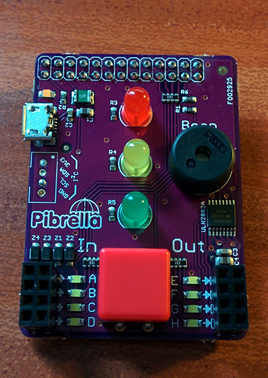
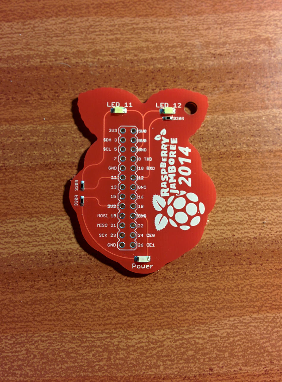
Blink is the ubiquitous blink example which flashes the LED on pin 0 (BCM_GPIO 17). Blink8 does a simple sequence of the first 8 pins/LEDs. (wiringPi numbers 0-7) I tested it on my ladder board. If you have a Pibrella board, then blink will toggle the Yellow LED. blink8 will run on it, but would need changing (left as an exercise to the user 🙂

  • pibrella.lmc

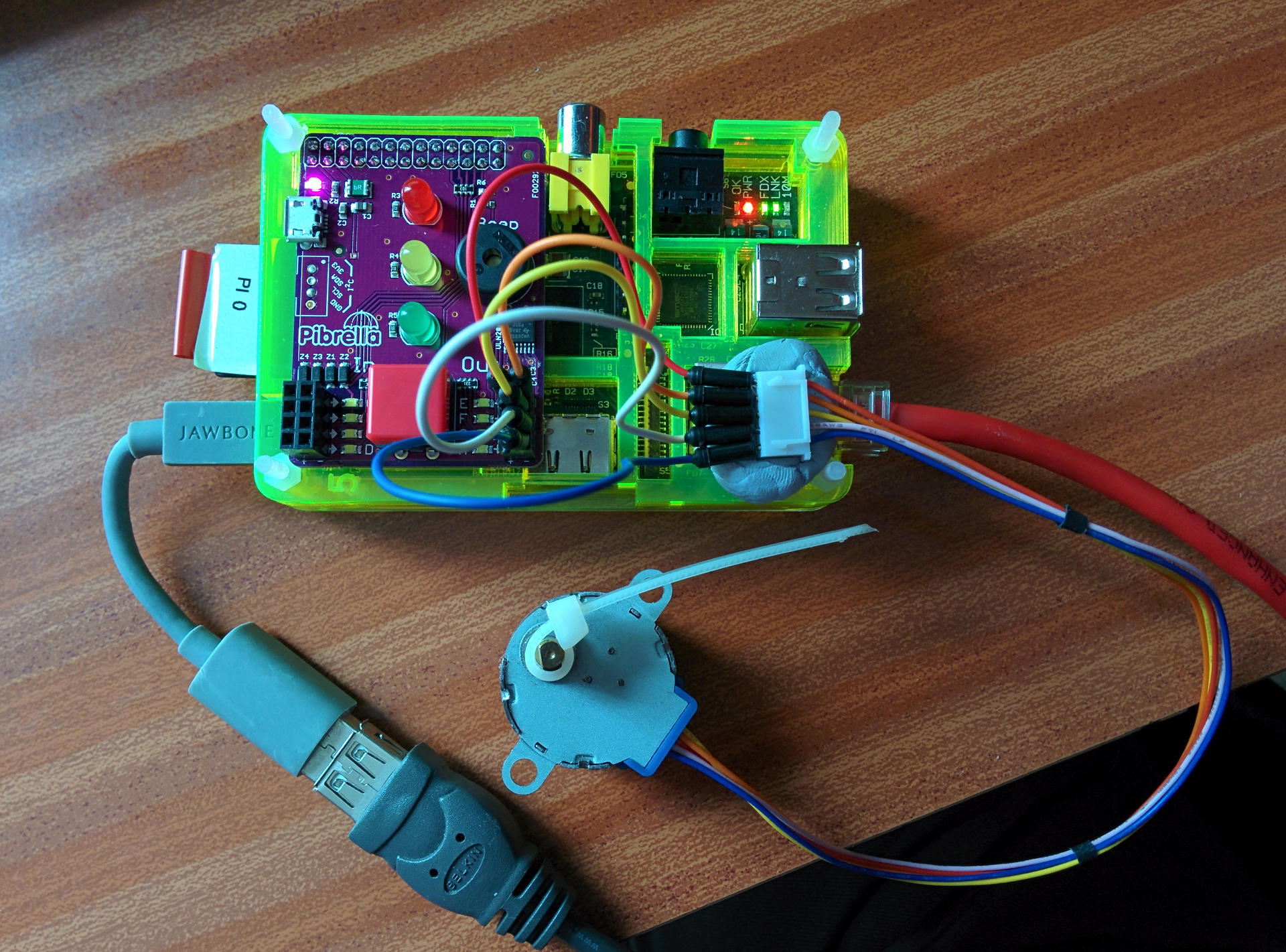
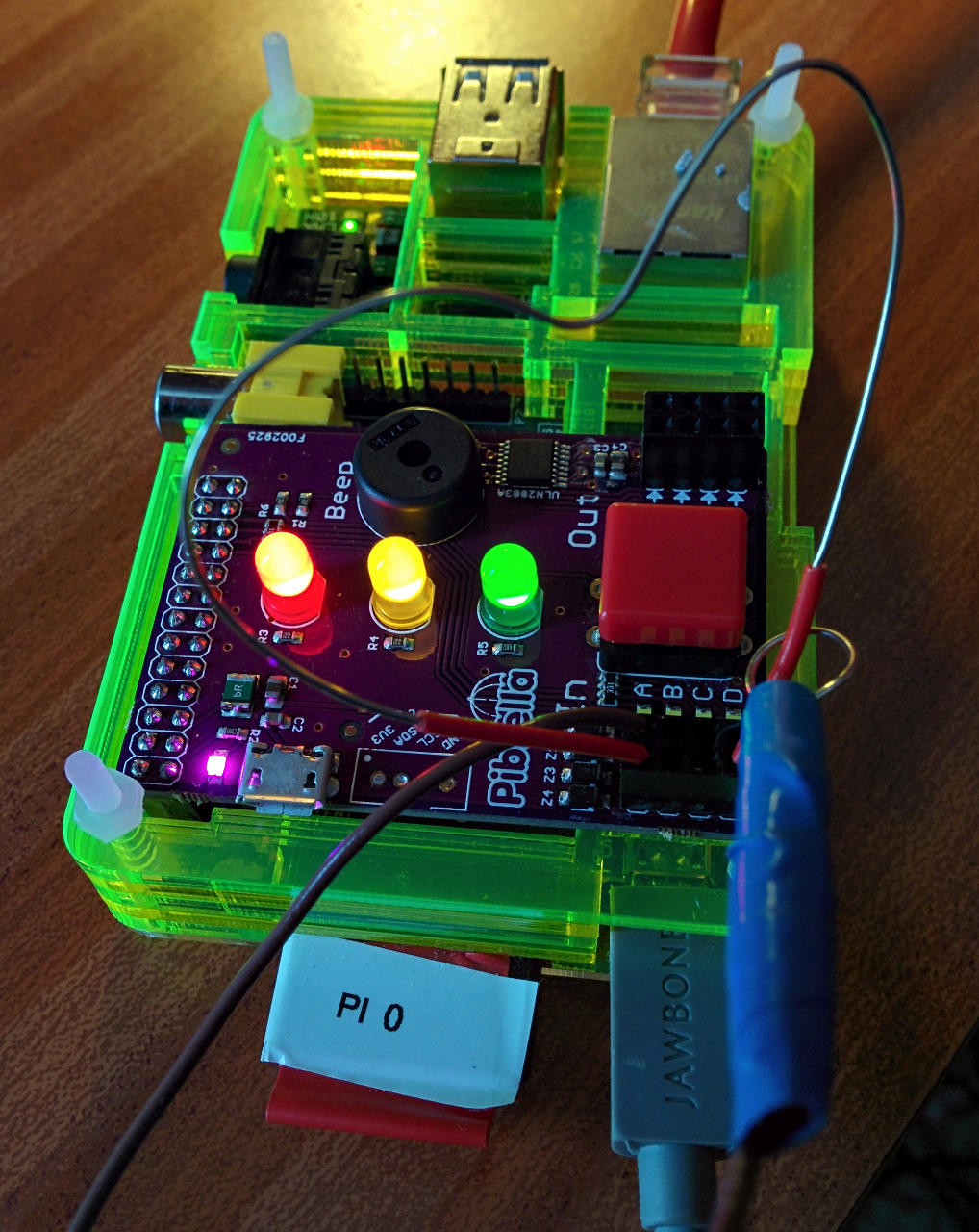
If you have a Pibrella board from Pimoroni plugged into your Pi, then this is a very simple traffic light program. Run it is slow mode. When started, it will light the Green LED and wait for the button to be pushed. When pushed, it will cycle green -> Yellow -> Red, then wait for 5 seconds or so, then cycle back again. It’s also a demonstration of the JSR/RET op-codes too.
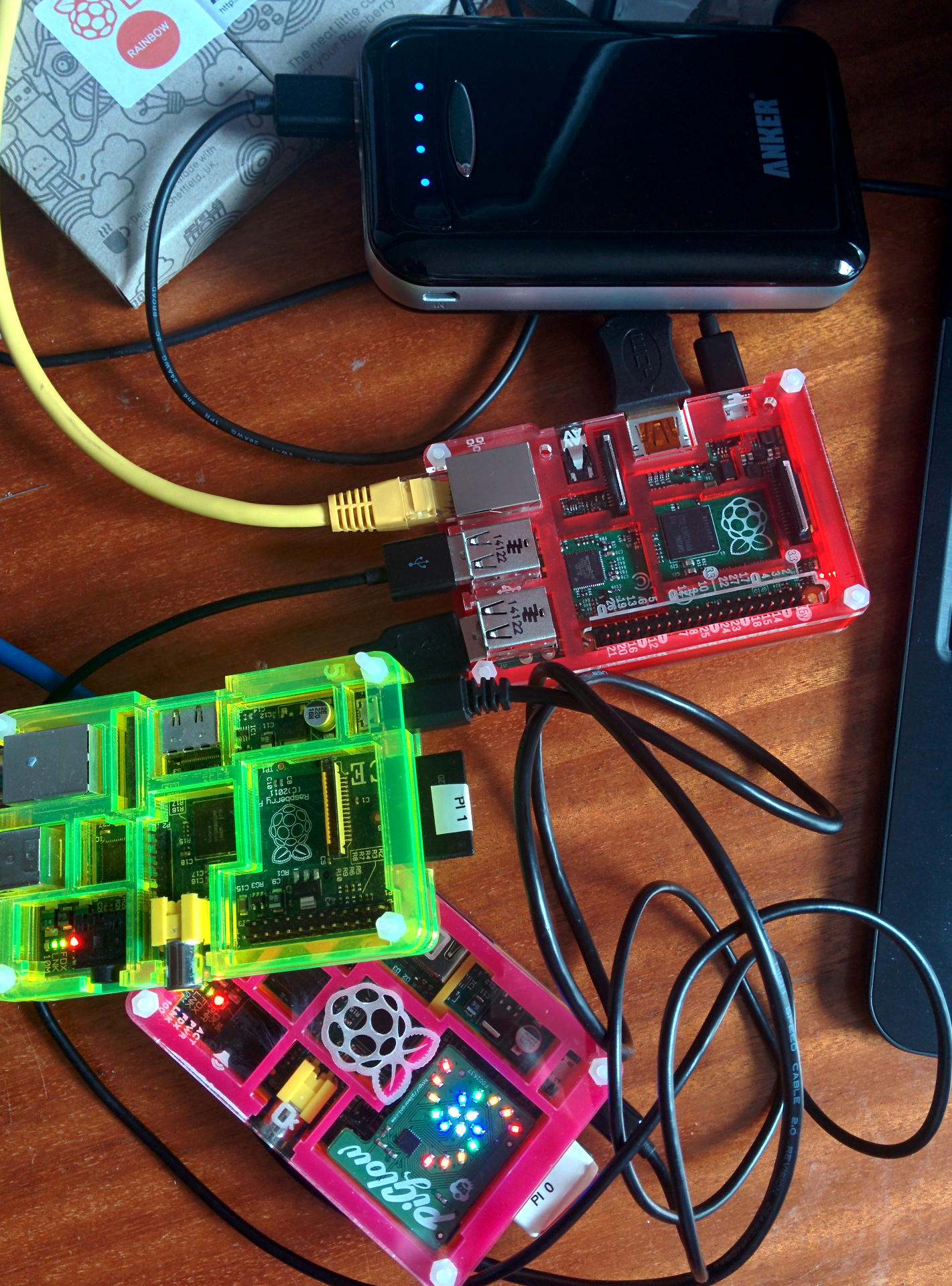
A Visit to the Center for Computing History

I had a few hours to spare today while I’m in Cambridge, so I decided to pay a visit to the Center for Computing History and what an exciting place it is! (Well, for an old geek like me that is!)

The Center for Computing history is a museum and charity, supported by your donations, so if you’re in Cambridge do pay it a visit if you can – it’s chock-full of … well … “stuff”. More Stuff, and even more stuff! (and behind the stuff – yes, you guessed it, even more stuff!)

When you think of museums, you think of places with stuffy old exhibits, but computing … well, it’s not that old, really. Sure, we have examples of computing devices or ideas centurys old, but for some – it’s still in our living memory – but it’s still important to preserve it all, especially as it changes so rapidly – e.g. today I saw some old computers that I never knew existed, yet they were built only 20-30 years ago!

As well as exhibiting computers (almost all are working too!), there is a great display of calculators (mechanical and electronic) and old gaming consoles – probably almost every single one including an old Atari Pong game. I wasn’t into console games that much – the Atari 2600 was about where I stopped, but I was amazed to found out that there were so many!

Go and sit in the Classroom of the 80’s – dozens of BBC Micros all working, enter BASIC programs into them, the PET, The Apple II and anything else turned on. Play on the Domesday machine – a BBC Micro and video disc combination – providing pictures and data from 1980’s Britain, controlled by a BBC Micro and trackball.

It would take too long to even think about listing the exhibits I saw here, but I took a few photos of things that are relevant to my computing life (so far!) Also – look at some of the exhibits – recognise them on TV? If you do, it’s highly likely they came from here, so if you’re planning a TV/Film type of thing and want some retro computers – this is the place to come!

The frst computer I really used a lot was the Apple II – and there are many here – this one is only display:

Apple //eThis is an Apple //e which was a follow on from the original Apple II computer. The 2 5.25″ floppy drives above it have a capacity of 130KB each (yes, Kilo Bytes!)

After the Apple II came the Apple ///

Apple ///I’ve only ever seen one other of these – in a computer shop in Edinburgh many many years ago! They didn’t sell too well, being eventually replaced by the Macintosh range of computers.

The Jupiter Ace:

jupiter AceAn interesting oddity was the Jupiter Ace. Designed by some of the Sinclair ZX Spectrum designers, it ran Forth rather than the more popular BASIC of the day. (Early 1980’s).  Sales were very low (under 10,000?)

In the late 1970’s three computers really stood out – the Apple II, Tandy TRS-80 and the Commodore PET. Early PETs had a somewhat odd keyboard, but they were an all-in-one solution with integrated storage (compact cassette) and VDU:

PET 2001This is one of the very early PET-2001’s with the calculator style keyboards. These were replaced with a bigger keyboard and the tape storage replaced with an external disk drive unit.

As well as some of the newer computers (new as in the last 35 years here!) there are a few older exhibits – Some old Ferranti Atlas computers, DEC PDP8 and 11’s and an Elliot 903. (Which I took a photo off, but didn’t check at the time, only to find now that it’s too badly out of focus to use) I had a summer job programming an Elliot 903 in about 1980 – even though it’s a computer that originated in the mid 1960s!

However is are a couple of old blasts from the past:

delayLineThis is a delay-line memory storage device. The principle is simple; Take a long piece of wire, connect a beeper to one end, and a sensor at the other. Pulse the beeper and wait for it to turn up at the far end, then feed that pulse back into the wire. The trick here is that you can send many pulses down the wire before the first one pops out at the end (speed of sound and all that). Keep them being re-generated and fed back in and you have a memory unit. It’s not fast, but devices like this did work and were in-use in many systems. (The predecessor to these were mercury columns!) This one stores about 1000 bytes.

Moving on a few years, we have:

coreThis is magnetic core memory. The link to it on the Computer museum site is here. It’s very old, hand made, possibly for an experimental computer or calculator. If you look closely, you can see the magnetic cores and the wires threaded through them. This block stores 20 x 14 = 28 bits of data… Later computers had much smaller cores and capacities up to 2 megabytes.

Our favorite British computer company, Acorn is well represented in the museum – starting with the Acorn System 1:

acorn1After the System 1, there was the Atom:

acornAtomwhich was the forerunner to the Acorn Proton – or as we know it; the BBC Micro:

masterCompactThis version is actually a Master Compact – a version of the BBC Master which was the successor to the BBC Micro in a separate keyboard + system case unit.

The history of Acorn is well documented and everyone in the world knows about them – or should do as the “A” in the ARM processor that powers their phone, set-top box, Raspberry Pi and a host of other devices stands for Acorn. (as in Acorn Risc Machine)

Finally, something that never made it:

phoebeThis was the last computer in the Acorn business range – codename “Phoebe”. It’s remarkable as it is an ARM based system supporting multiple CPUs and the now industry standard PCI slots for expansion – as well as a relatively modern and fast graphics system. Literally a day before the launch, Acorn decided to withdraw from the business market and concentrate on other things.

So there you are – just some of my highlights of a visit to the Center for Computing History in Cambridge. If you have time to spare, then go and visit and experience everything. (And if Jason is about, tell him I sent you and ask for a quick peek from the top of the stairs 😉

BASIC is 50

So today (30th April, 2014)  marks the 50th anniversary of the BASIC programming language! Hurrah!

The very first BASIC program:

10 LET X = (7 + 8) / 3
20 PRINT X
30 END

To help celebrate this, I’ve made a new release of my RTB – Return To BASIC interpreter for the Raspberry Pi. RTB started life about 2.5 years ago – even before the Raspberry Pi hardware was on-sale. I wasn’t initially thinking about the Pi, just Linux in-general, but since the release of the Pi, it has gained a small and growing userbase. Get your copy of RTB for the Raspberry Pi here.

Which I think is fantastic for a 50 year old language!

For the past year (ish) I’ve actually been devoting my BASIC time to a forked version called FUZE. This is to run on the FUZE hardware platform, but I’ve just taken the steps to get RTB caught up with the FUZE version and am releasing it today in an easy to use way to install and run on your Raspberry Pi.

So say happy birthday to a 50 year old language and go and write that BASIC program you’ve always wanted to write… You know the one:

10 PRINT "BASIC IS AWESOME!"
20 GOTO 10

Of-course, in modern RTB, that would really be:

cycle
  print "BASIC is Awesome!"
repeat

Pibrella from Pimoroni

Some time back the boffins at Pimoroni sent me a prototype of the new Pibrella board with a view to making the little piezo speaker on it make some noise… It wasn’t that loud, so I made a few suggestions then… Last Wednesday, almost as I was leaving for the Manchester Pi Jamboree the production version dropped through my door, and here it is!

pibrellaIt’s a tiny little board that fits on-top of the Raspberry Pi aimed at helping to teach programming using some big LEDs and a button to help make it more exciting.

Features

  • 3 Large LEDs; Red, Yellow and Green
  • A Big Red button! (Everyone needs a Big Red Button!)
  • 4 Inputs – which have a degree of protection on them via a resistor and zener diode with LEDs to indicate the input state.
  • 4 outputs – which are Open Collector outputs from a ULN2003 open collector driver chip, also with LEDs to indicate their state.
  • A piezo buzzer which can generate tones, notes and other little squawks.
  • Its own website here: http://pibrella.com/

It’s also purple which is their trademark board colour (as used in the PiGlow too, and who knows what in the future)

It’s aimed at helping to teach programming and simple GPIO use.

From the Pi’s GPIO point of view, it’s just simple outputs and inputs, so I didn’t think it warranted a special wiringPi devLib driver (unlike e.g. the PiGlow), but I have put together a nice header file for use in your C programs with all the input and output definitions and written a few test program for it in C and BASH, so if C is your thing, then read on. (If not, then read on anyway, you might get some ideas!)

You can fetch and compile my code and files as follows:

git clone git://git.drogon.net/pibrella
cd pibrella
make

All these examples will require the wiringPi libraries installed. Get them here.

The key part of all this is the file: pibrella.h. This contains all the pin definitions and some functions to help you use the Pibrella board from your C programs using wiringPi.

Please do look at the sources for the various programs here to find out how to use it effectively.

The examples I’ve provided are:

  • tune – Plays a well knows tune!
  • ladder – my old ladder game altered for the Pibrella board
  • tuxx.sh – my old Tuxx (Pelican) road crossing simulator
  • stepper – how to drive a micro stepper motor directly from the Pibrella.
  • step1 – Drive a stepper motor one step at a time using the Big Red Button.
  • wire – classic wire loop agility game – move the wire loop along the bendy wire without touching it. Three touches and you’re out!

Tuxx/UK Road Crossing

Start with tuxx.sh – it’s a simulation of a UK “pelican” road crossing, written in BASH using the wiringPi GPIO command. Run it as follows:

./tuxx.sh

It will initialise and start with the Green LED on and the “red man” (top LED in the block of 4 white LEDs on the right) on. That means traffic can go, pedestrians should not walk.

Push the button and the sequence will start – Green,  Yellow, Red to signal the traffic to stop, then the red man will change to the green man (bottom LED in the block of 4 white LEDs on the right) and the beeper will beep. After the allotted time, the sequence will change to flashing green man and Yellow, then red man and Green to allow traffic to pass again.

Tunes/Notes

The tune program is just a demo of using and making tones with your own software. Run it with the usual:

sudo ./tune

and name that tune…

I will warn you now; the sound quality isn’t great. It’s a very small piezo device with some resonant frequencies that don’t quite match playing musical notes…

Ladder

This is my old ladder game. You start off at the bottom and have to climb to the top. The bottom LED will flash and to climb, you push the button. However you can only push the button down while the LED is on. If you push it while it’s off, then you fall to the bottom again. When you get to the top (the Red LED) then you win! Note that the closer to the top you get the harder it becomes… You may need to push the button 2 or 3 times to jump just one LED, but don’t keep it pushed, or back to the bottom you’ll go!

Run it with:

sudo ./.ladder

and enjoy the fun.

Stepper Motors

The uln2003 open collector driver chip on the Pibrella is capable of driving one of the little micro stepper motors (e.g. 28BYJ). You’ll have to make up some more wires as these usually come with a socket designed for a PCB plug:

pibrellaStepperThe photo shows how its wired up. The stepper motor has wires coloured Red, Orange, Yellow Pink and Blue. These go via male to male jumpers into the Pibrella in the same order for the Orange, Yellow, Pink and Blue – from top to bottom on the outermost set of 4 pins on the right-hand connector. The Red wire from the stepper goes to one of the 4 innermost pins on the right-hand connector (This is the +5v supply). Note that I didn’t have a pink jumper lead, so I used a white one here.

I’ve written 2 little programs, one; stepper simply makes it do a full turn one way, then a full turn the other, and the 2nd; step1 uses the button to advance the motor one step at a time. You can see which outputs are active on the 4 little white LEDs as the motor turns. (It’s 4096 pulses per full turn, so be patient if you want to make it go a full turn!

Wire

This is the classic steady-hand wire-loop game. Your task is to firstly make it, and secondly to guide the wire loop over the curvy wire to the other end without touching the wire!

I made up a very small version just for demonstration:

wireThe bendy wire (with red insulation at the ends) is plugged into the top and bottom of the outside column left-hand connector. (All these pins are at 3.3v). The wire loop you hold is plugged into the innermost connector on the same block marked “A”

We run the program:

sudo ./wire

and off we go. The program initially waits for the wire to be clear, then the game starts. You are allowed three touches of the wire which will be accompanied with a beep and one of the LEDs lighting (starting with Green and ending with the Red one), and on the fourth touch it’s game over. The Big Red Button can be used to reset the game at any time.

Summary

The Pibrella board is a fun little board that can be used on its own, or in conjunction with many other little projects – you just need to get thinking and get programming! Python and Scratch libraries are available and now this lets you program in it BASH, C or anything else that supports wiringPi – e.g. BASIC.

Raspberry Pi Jamboree 2014

So the 2nd (annual?) Jamboree was held in Manchester thanks to Alan O’Donohoe and whole host of others who helped him arrange it and it went fantastically well!

This year it was spread over 2 days with some talks, etc going on on Thursday with the main event in a dedicated room on Friday where there were some more specialised talks going on.

Of-course the real main event was the party in the evening, celebrating not just the Jamboree but of-course the Raspberry Pi’s 2nd birthday!

PANO_20140228_172403That’s a (slightly wobbly) panoramic view of the party room.

I was on the FUZE stand for some of the time, didn’t take that many photos in the end, here’s a couple:

fuzeStandThis is a FUZE running a BASIC program that lets you move the control icons around the screen then push them to move to robot arm…

displayThe new DSI display interface adapter board from the Raspberry Pi Foundation!

alanInternational man of mystery; Alan O’Donohoe…

At the party there was lots of “swag” to be had – little bits and pieces from lots of people and a couple got together to produce this nice little GPIO shim:

jamboreeThis was designed by Andrew @gbaman1 and @minigirlgeek and has a power LED and 2 programmable LEDs on pins 11 and 12 – BCM_GPIO 17 and 18, or wiringPi numbers 0 and 1. Here are a few wiringPi examples to use them: (using the gpio command-line tool)


# Make the pins outputs
gpio move 0 out ; gpio mode 1 out
# Light them up!
gpio write 0 1 ; gpio write 1 1
# Make them flash:
while true; do gpio wb 1 ; sleep 0.5 ; gpio wb 2 ; sleep 0.5 ; done

That last line uses the ‘wb’ command – wite byte which outputs an 8-bit number to the pins – alternating bits 0 and 1 here.

And finally… If you’re missing me talking about bread, here’s some I made earlier. Devon cider bread!

ciderBread


Bread making with the Artisan Bakery School

So I’ve been making bread for a good number of years now, mostly self-taught, and even sourdough for a few years now, and as I’m sure you’re aware there has been a veritable plethora of baking programs on TV recently – from Paul “silver fox” Hollywood, the Great British Bake-Off to the Fabulous Baker Brothers and who knows what else might be shown on daytime TV, etc… All showing you how to make real bread, but never really going into any great detail…

So, while my bread making was fine, I’ve always felt it could be improved and as one of my many mottos is “learn something new”, I embarked on an artisan bread making course with Dragan and Penny at the Artisan Bakery School in Sparkwell, Devon.

And what a fantastic day it was – actually, I should say two days as I’ve visited them twice now. The first time as an introduction to their sourdough bread making and the second to look closer at the business  side of things – (The micro business blueprint) going through some of the issues they faced and their solutions, pitfalls and traps and so on. Both times we baked some fantastic bread and my own skills have improved dramatically. Dragan and Penny inspired confidence and showed me new techniques for kneading and shaping, and even right after my first visit with them my bread improved – literally overnight!

Dragan’s technique for kneading was excellent and much faster than my own – but after several years of doing it my way, its been somewhat challenging to adapt to his way – it’s not that different at the end of the day, but it’s more efficient, or seems so – if you had to hand knead dough for over 100 loaves one Christmas eve, as they did a few years back, I guess you get efficient quite quickly!

And on to shaping – who would have thought just how important that was – it’s demonstrated quickly with a flourish on TV and in some books, almost glossed over, but seeing it first hand and then seeing the difference in the resulting loaf was very good – even in terms of cooked loaf volume – on the course, we were using slightly less dough per loaf than I was in my kitchen, yet the loaves were rising higher with a better texture than my own… All down to the shaping, slashing and proving technique!

Other techniques – how to test the dough for readiness, how to slash the perfect shape on-top, baking baguettes, rolls (soup buns as Dragan calls them!) and different shape loaves. Different flours – we made rye bread – both a standard sourdough rye with added seeds, nuts, etc. to a classic Borodinski (which tastes utterly fantastic!)

gbreadThat’s me with the bread we made on the last course – I didn’t make it all though – there were two others on the course that day, but it’s still a lot of bread!

So my own bread now which is being sold in The Seed in Buckfastleigh will certainly benefit from this, and I not have a bit of a clearer head on the business side when I decide to expand the Moorbakes business side of it all.

Techcamp 2013 (Raspberry Pi)

So the past two weeks has seen me attending Techcamp 2013 held at at Sparsholt college just outside Winchester. I was the lead tutor for their Raspberry Pi course. And now, a few days later I’ve finally had enough sleep to type this up 😉

Techcamp is run by Tom Ward, an Electrical Engineer who previously worked as Head of Science at Elstree School, Berkshire. Tom believes that young people should have ever opportunity to enjoy a summer camp from a technical perspective as opposed to those other summer camps where you play sports, etc… (Although Laser Tag is an active outdoor sport played here!)

A few months ago Tom was looking for some Raspberry Pi people and I replied to his posting and before I knew it, was in the system… Young people (8 to 17 year old!) attending the camp had to pick 2 courses to do over the week. The camp ran for two weeks and a very small number of young people stayed for both weeks, (attending 4 courses), but the majority were one week only.

Helping me with the Raspberry Pi class was Andrew Mulholland who flew over from N. Ireland for the fortnight.

The young people are split into day and residential “campers” and the residential ones arrive on the Sunday afternoon… So evening activities are arranged, to encourage people to get to know each other.

Sunday evening on the first week: We gave the young people some cardboard, tape and scissors and had them build a bridge that had to take firstly the weight of the lightest camper, and secondly Tom…

Most groups went for the “brick” approach where they just taped as much cardboard together as they could, but one group went for a proper engineering approach with a simple arched brdge which worked very well indeed!

The second week’s first night challenge was to build a tower with spagetti and marshmallows – sadly rain stopped play, but we did get a few structures built:

The rain produced a spectacular double-rainbow though:

rainbowsAnd on to the classes… I had 14 young people in my morning class and 13 in the afternoon on the first week and 2 groups of 12 people the second week. The camp fees included a “lab fee” to cover materials used and the students got to take home their Raspberry Pi, case, keyboard, mouse and SD card.

One of the challenges was to make the classrooms computer friendly – and the one we had been allocated had a grand total of one Ethernet point, but plenty of Wi-Fi. We had no Wi-Fi adapters for the Pi’s so some creativity was required involving re-arranging the desks, 3 Ethernet switches (actually, one was a 20 year old 10mB hub!) a lot of gaffer tape and an area I dubbed “the valley of death”.

I also wanted to create lots of space so that myself and Andrew could easilly move round the students to give them help and assistance and so on. I think it worked out well given the situation, and the whiteboard and smart-boards at the front were visible.

The smartboard was driven directly by a Raspberry Pi, but without drivers, there was no on-screen keyboard, but the touch/mouse input worked very well for Scratch but less-so when we had to type stuff in.

This was the first year Techcamp ran the Pi course – not a surprise given how relatively new the Pi still is, so it was hard to gauge what to do – the course was billed as an introduction to the Raspberry Pi and some game playing and programming – e.g. Minecraft… So we started by giving a general introduction to the Pi, some command-line activities – the first “Hello world” using BASH, then moved onto some simple programming with Scratch – Hello kitty, and turtle graphics. We moved onto BASIC with more turtle graphics then got the students to start to modify some of the programs I’d written to give them experience with looking at other code – my little snake game went down well with the students hacking it to change colours and alter the colission mechanisms (ie. to cheat snake death!)

After that we moved on to Python and took a more traditional approach (next year I’ll do more turtle graphics in Python) and then we looked at GPIO. We started with a simple LED+Resistor circuit on a breadboard when we wrote a program in BASIC, then Python to blink out S.O.S in morse code, then we used my ladder board whith more LEDs and buttons.

Finally it was minecraft time (for those who wanted to play it – some wanted to keep on with the ladder board and more code to use it) – with the caveat that they could only play the Pi version of Minecraft if they wrote some Python to interface to the Minecraft server. We had some intersting bits of code there – random dirt blocks in the sky – “competitive” teleporting of characters, auto-laying of TNT as you move and so on.

The camp was run over 2 weeks, but over the weekend between the two main weeks, we had a dozen students who werestaying both weeks to look after… So we hired a minibus and took them to various local attractions. InTech science center was a big hit and the Portsmouth Royal Navy Museum was another.

  • Note to anyone else doing this – sadly, Portsmouth is hostile to minibuses with one-way streets leading into car parks too small for a minibus. I found one area of street parking suitable for coaches, but it was a good 10 minutes walk from the Entrance of the museum – not good when you have a dozen excited young people in tow!

But apart from that, a good day was had by all:

onboardalthough I’m not sure Nelson would approve young people cavorting round on the Victory though…

Techcamp was about young people and technology – and it would be unfair of me to leave out the other courses that were run over the fortnight – Model rocketry, Robotics, building a pair of  Laser Tag guns (Parents – expect your child to get burnt by a soldering iron!) games and web design, not to mention the lighter evening activities forthe residential campers (“Reverse engineering” was particularly well enjoyed!) and the staff entertainement night for the young people – Felix and his amazing non-newtonian liquid kitchen chemistry, Jack and his gravity defying physics and myself with my make a Raspberry Pi(e) from scratch demo…

It was a pretty amazing 2 weeks for me. Very enjoyable and I’m already planning for next year!