Last weekend (Saturday the 2nd to be precise!) I visited The National Museum of Computing (aka TNMoC) which is based in the grounds of Bletchley Park.
This was my 2nd visit and I was especially interested in seeing the newly rebooted WITCH in operation and I wasn’t disappointed!
However, first things first. TNMoC is situated in the grounds of Bletchley Park and as well all know, Bletchley Park is home to the WWII code-breakers where they built the machines that decoded the Enigma, (Bombe), Lorenz (Colossus), and who knows what other ciphers and codes during WWII.
It’s important to note that TNMoC is a separate entity to Bletchley Park! They pay rent to Bletchley Park for the bunkers they occupy. That means you pay separately to get into TNMoC and an entry ticket to one does not give you entry into the other.
Currently (Dec. 2012) it’s £12 to get into Bletchley Park and £5 to get into TNMoC, however a slight confusion is that the Colossus and Tunny galleries are part of TNMoC even though they may appear to be part of Bletchley Park, and if you want to visit these, then there is a £2 surcharge on-top of your Bletchley Park fee – but that’s redeemable against the full price of a ticket into TNMoC (you then just pay £3).
Confused? I was, and so are many others, so to recap:
- Entry to Bletchley Park to see the Enigma and Bombe displays is £12.
- Colossus is owned by The Colossus rebuild company and is on long-term loan to TNMoC.
- Entry to TNMoC is £5.
- If you want to see the Colossus and Tunny galleries then it’s included in TNMoC entry but it’s a £2 surcharge if you just want to see the Bletchley Park (Enigma and Bombe) exhibits.
- If you paid the £2 surcharge to see the Colossus, and subsequently want to see TNMoC, you only pay the balance of £3 to get into TNMoC.
There is also a £3 car parking fee on-top of that, but I’m not sure if that just applies to BP or to either BP or TNMoC.
So, back to TNMoC:
The WITCH computer is the oldest running digital computer on the planet and I wanted to see it in operation.

The WITCH control panel
WITCH is the Wolverhampton Instrument for Teaching Computation from Harwell – It is essentially a programmable calculator – reading programs and numbers from 6 tape readers, feeding them through its relays, circuits and decatron tubes and producing results on a connected printer. The design was started in 1949 and it ran its first program in 1951. You can read the full story on the TNMoC website.
So I spent quite some time watching it, listening to it and trying to understand what I could of how it works. One day I’ll write a full-blown simulator for it, but not today…
The rest of TNMoC is still fascinating – as well as some of the older computers – IBM , Marconi, Ferranti, Digital (PDP) and so on, there is also a modern (well to me!) selection of microcomputers – starting with the Apple II, going through other variants – the BBC Micro, Spectrum and many others – right up to modern day organisers and the “smartphones” they’ve all more or less become now.
And something that should have been better/popular, but just didn’t make it…. Won’t tell you what, but the keyboard has an “Oops” key on it! (Ok, I will tell you, it was the PERQ!)
They also have some computers that are not that old (relatively speaking!), but completely unknown to me. Just keep looking and asking and you’ll find something you’ve never seen before, and at the end of the long corridor is the BBC Micro room – anyone who was a teenager in the 1980’s in a school in the UK will immediately recognise them and the bits and pieces connected to them.
Finally there is a little cafe and shop – they do nice hot chocolate and (I have to say) although it’s small and doesn’t do food other than biscuits/cakes, I’d go there any day over the canteen in BP!
However, while I thoroughly enjoyed my visit, it wasn’t without issue – the confusion between BP and TNMoC was one, but also I felt that TNMoC was lacking “something”. I suspect a proper sense of direction, but I know that it’s all staffed by volunteers who do a great job, but …
What I’d like to see is more “hands-on” stuff. I spent some time showing my wife how punched paper tape works – and just happened to use a handy TTY33 to help demonstrate it – however that TTY33 had a “do not touch” sign nearby, but hey, what’s a sign…. However that’s an issue. I feel we need more hands on things like that – there is a room with that lovely smell of warm machine oil, but just lots of what looks like junk lying about. What about a few TTY33’s with working tape punches and readers for kids (young and old!) to play with… Connect one up to a computer running BASIC for that proper authentic time-sharing experience… Get one to run “Eliza” and so on…. Hunt the Wumpus, there’s loads of old stuff like that that might be amusing to some…
So there you go – TNMoC – A great place. Visit it you can!
As for Bletchley Park… It’s fine too, but I’m not sure I’ll visit that part of the grounds again – and especially not the canteen )-: Very disappointing there… Take a packed lunch and get into the cafe at TNMoC for a hot chocolate!

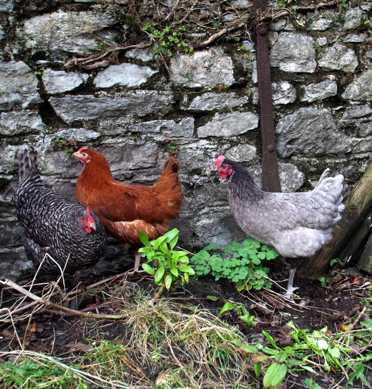 Our chickens. They are (from left to right), a Speckledy Maran, a Colombian Black Tail and a Blue Maran.
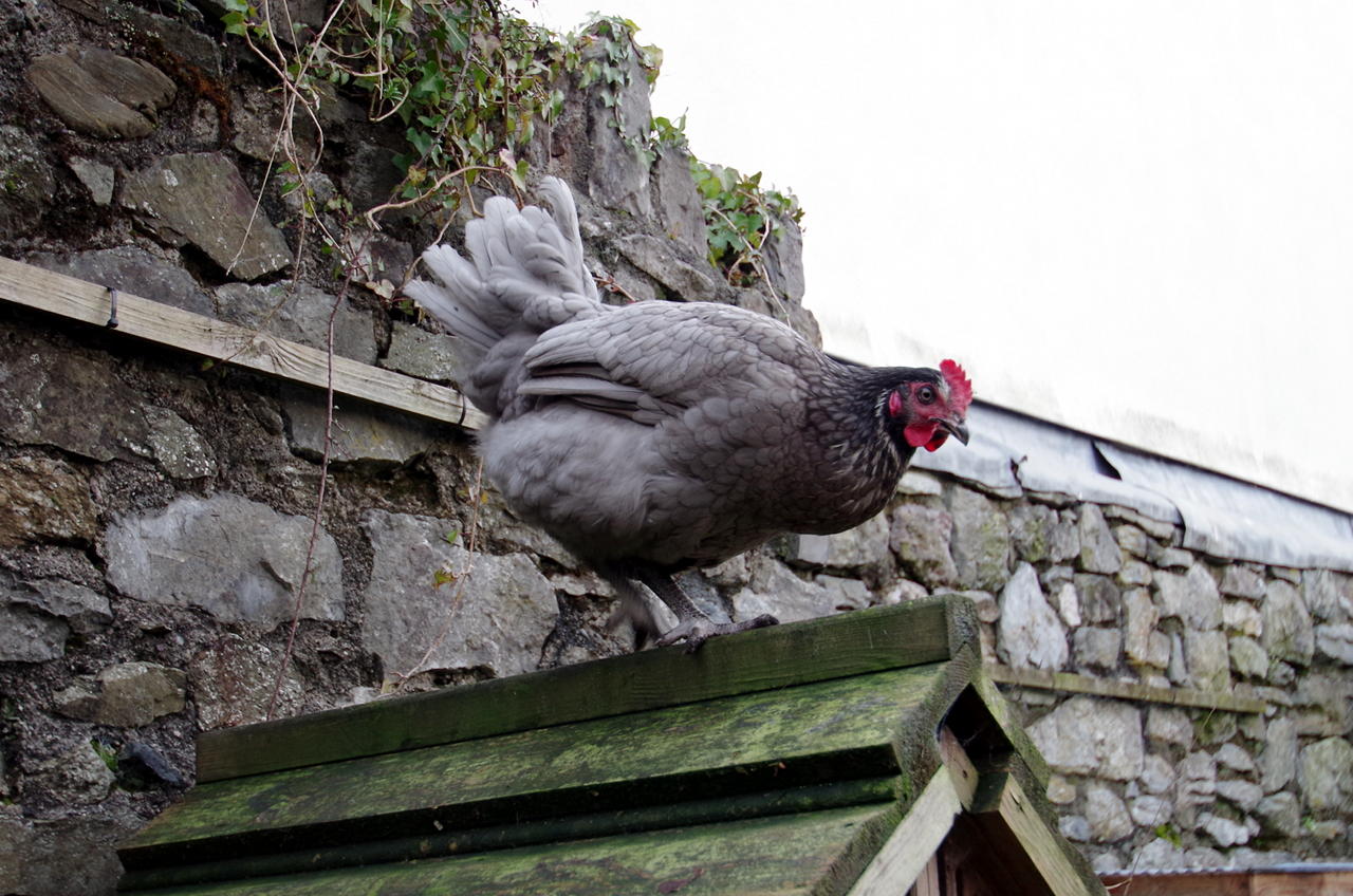 Ginger – the escape artist
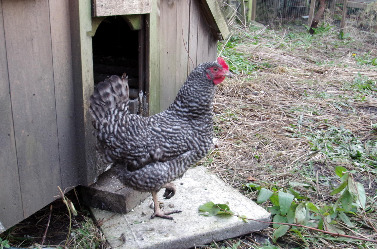 Edith II
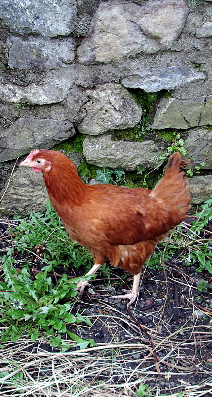 The Drug Baron
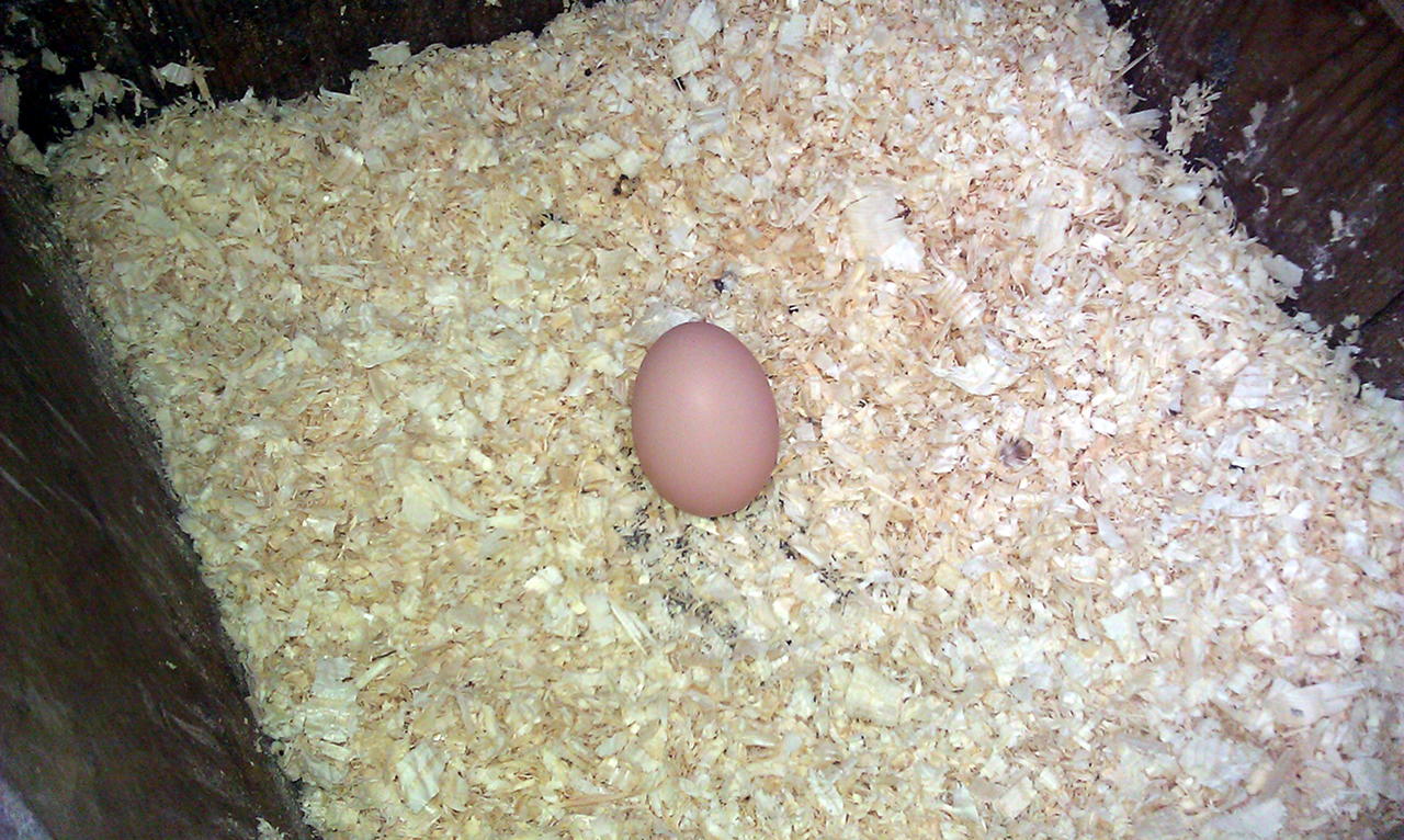 Not 100% sure which chicken, but I suspect it’s Edith II that’s laying so-far.